
Project Gutenberg's Stargazing: Past and Present, by J. Norman Lockyer

This eBook is for the use of anyone anywhere in the United States and most
other parts of the world at no cost and with almost no restrictions
whatsoever.  You may copy it, give it away or re-use it under the terms of
the Project Gutenberg License included with this eBook or online at
www.gutenberg.org.  If you are not located in the United States, you'll have
to check the laws of the country where you are located before using this ebook.

Title: Stargazing: Past and Present

Author: J. Norman Lockyer

Release Date: September 30, 2016 [EBook #53172]

Language: English

Character set encoding: UTF-8

*** START OF THIS PROJECT GUTENBERG EBOOK STARGAZING: PAST AND PRESENT ***


Produced by Richard Tonsing, Chris Curnow and the Online
Distributed Proofreading Team at http://www.pgdp.net (This
file was produced from images generously made available
by The Internet Archive)
Transcriber's Note:
The cover image was created by the transcriber and is placed in the public domain.

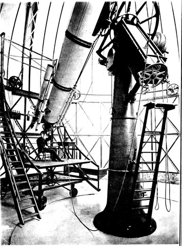
R. S. NEWALL’S TELESCOPE.
In the year 1870 I gave a course of eight Lectures on Instrumental Astronomy at the Royal Institution. The Lectures were taken down by a shorthand writer, my intention being to publish them immediately. In this, however, I was prevented by other calls upon my time.
In 1875 my friend Mr. Seabroke generously offered to take the burden of preparing the notes for the press off my shoulders; I avail myself of this opportunity of expressing my very great obligations to him for his valuable services in this particular as well as for important help in the final revision of the proofs.
On looking over the so completed MSS., however, I saw that the eight hours at my disposal had not permitted me to touch upon many points of interest which could hardly be omitted from the book. Besides this, the progress made in the various instrumental methods in the interval, and the results obtained by them, had been very remarkable. I felt, therefore, that the object I had in view, namely, to further the cause of physical astronomy, viby creating and fostering, so far as in me lay, a general interest in it, and by showing how all departments of physical inquiry were gradually being utilized by the astronomer, would only be half attained unless the account were more complete. I have, therefore, endeavoured to fill up the gaps, and have referred briefly to the new instruments and methods.
The autotype of the twenty-five inch refractor is the gift of my friend Mr. Newall, and I take this opportunity of expressing my obligation to him, as also to Messrs. Cooke, Grubb and Browning for several of the woodcuts with which the chapters on the Equatorial are illustrated; and to Mr. H. Dent-Gardner for some of those illustrating Clock and Chronometer Escapements, and for revising my account of them.
Nor can I omit to thank Mr. Cooper for the pains he has taken with the woodcuts, especially those copied from Tycho Brahe’s description of his Observatory, and Messrs. Clay for the careful manner in which they have printed the book.
| BOOK I. | ||
| THE PRE-TELESCOPIC AGE. | ||
| CHAP. | PAGE | |
|---|---|---|
| I.— | The Dawn of Stargazing | 1 |
| II.— | The First Instruments | 16 |
| III.— | Hipparchus and Ptolemy | 25 |
| IV.— | Tycho Brahe | 37 |
| BOOK II. | ||
| THE TELESCOPE. | ||
| V.— | The Refraction of Light | 55 |
| VI.— | The Refractor | 73 |
| VII.— | The Reflection of Light | 90 |
| VIII.— | The Reflector | 100 |
| IX.— | Eyepieces | 109 |
| X.— | Production of Lenses and Specula | 117 |
| XI.— | The “Optick Tube” | 139 |
| XII.— | The Modern Telescope | 152 |
| viiiBOOK III. | ||
| TIME AND SPACE MEASURERS. | ||
| XIII.— | The Clock and Chronometer | 175 |
| XIV.— | Circle Reading | 211 |
| XV.— | The Micrometer | 218 |
| BOOK IV. | ||
| MODERN MERIDIONAL OBSERVATIONS. | ||
| XVI.— | The Transit Circle | 233 |
| XVII.— | The Transit Clock and Chronograph | 253 |
| XVIII.— | “Greenwich Time,” and the Use Made of It | 271 |
| XIX.— | Other Instruments Used in Astronomy of Precision | 284 |
| BOOK V. | ||
| THE EQUATORIAL. | ||
| XX.— | Various Methods of Mounting Large Telescopes | 293 |
| XXI.— | The Adjustments of the Equatorial | 328 |
| XXII.— | The Equatorial Observatory | 337 |
| XXIII.— | The Siderostat | 343 |
| XXIV.— | The Ordinary Work of the Equatorial | 349 |
| ixBOOK VI. | ||
| ASTRONOMICAL PHYSICS. | ||
| XXV.— | The General Field of Physical Inquiry | 371 |
| XXVI.— | Determination of the Light and Heat of the Stars | 377 |
| XXVII.— | The Chemistry of the Stars: Construction of the Spectroscope | 386 |
| XXVIII.— | The Chemistry of the Stars (continued): Principles of Spectrum Analysis | 401 |
| XXIX.— | The Chemistry of the Stars (continued): The Telespectroscope | 422 |
| XXX.— | The Telepolariscope | 441 |
| XXXI.— | Celestial Photography.—The Ways and Means | 454 |
| XXXII.— | Celestial Photography (continued): Some Results | 463 |
| XXXIII.— | Celestial Photography (continued): Recent Results | 469 |
| FIG. | PAGE | |
|---|---|---|
| 1. | The heavens according to Ptolemy | 3 |
| 2. | The zodiac of Denderah | 7 |
| 3. | Illustration of Euclid’s statements | 10 |
| 4. | The plane of the ecliptic | 13 |
| 5. | The plane of the ecliptic, showing the inclination of the earth’s axis | 14 |
| 6. | The first meridian circle | 20 |
| 7. | The first instrument graduated into 360° (west side) | 21 |
| 8. | Astrolabe (armillæ æquatoriæ of Tycho Brahe) similar to the one contrived by Hipparchus | 26 |
| 9. | Ecliptic astrolabe (the armillæ zodiacales of Tycho Brahe), similar to the one used by Hipparchus | 28 |
| 10. | Diagram illustrating the precession of the equinoxes | 31 |
| 11. | Revolution of the pole of the equator round the pole of the ecliptic caused by the precession of the equinoxes | 32 |
| 12. | The vernal equinox among the constellations, B.C. 2170 | 34 |
| 13. | Showing how the vernal equinox has now passed from Taurus and Aries | 34 |
| 14. | Instrument for measuring altitudes | 35 |
| 15. | Portrait of Tycho Brahe (from original painting in the possession of Dr. Crompton, of Manchester) | 39 |
| 16. | Tycho Brahe’s observatory on the island of Huen | 43 |
| 17. | Tycho Brahe’s system | 46 |
| 18. | The quadrans maximus reproduced from Tycho’s plate | 48 |
| 19. | Tycho’s sextant | 50 |
| 20. | View and section of a prism | 56 |
| xii21. | Deviation of light in passing at various incidences through prisms of various angles | 57 |
| 22. | Convergence of light by two prisms base to base | 59 |
| 23. | Formation of a lens from sections of prisms | 60 |
| 24. | Front view and section of a double convex lens | 61 |
| 25. | Double concave, plane concave, and concavo-convex lenses | 61 |
| 26. | Double convex, plane convex, and concavo-convex lenses | 62 |
| 27. | Convergence of rays by convex lens to principal focus | 62 |
| 28. | Conjugate foci of convex lens | 63 |
| 29. | Conjugate images | 64 |
| 30. | Diagram explaining Fig. 29 | 64 |
| 31. | Dispersion of rays by a double concave lens | 65 |
| 32. | Horizontal section of the eyeball | 66 |
| 33. | Action of eye in formation of images | 68 |
| 34. | Action of a long-sighted eye | 69 |
| 35. | Diagram showing path of rays when viewing an object at an easy distance | 70 |
| 36. | Action of short-sighted eye | 71 |
| 37. | Galilean telescope | 73 |
| 38. | Telescope | 75 |
| 39. | Diagram explaining the magnifying power of object-glass | 76 |
| 40. | Scheiner’s telescope | 78 |
| 41. | Dispersion of light by prism | 80 |
| 42. | Diagram showing the amount of colour produced by a lens | 81 |
| 43. | Decomposition and recomposition of light by two prisms | 83 |
| 44. | Diagram explaining the formation of an achromatic lens | 84 |
| 45. | Combination of flint- and crown-glass lenses in an achromatic lens | 86 |
| xiii46. | Diagram illustrating the irrationality of the spectrum | 87 |
| 47. | Diagram illustrating the action of a reflecting surface | 91 |
| 48. | Experimental proof that the angle of incidence = angle of reflection | 92 |
| 49. | Convergence of light by concave mirror | 94 |
| 50. | Conjugate foci of convex mirror | 94 |
| 51. | Formation of image of candle by reflection | 95 |
| 52. | Diagram explaining Fig. 51 | 96 |
| 53. | Reflection of rays by convex mirror | 98 |
| 54. | Reflecting telescope (Gregorian) | 101 |
| 55. | Newton’s telescope | 102 |
| 56. | Reflecting telescope (Cassegrain) | 103 |
| 57. | Front view telescope (Herschel) | 103 |
| 58. | Diagram illustrating spherical aberration | 105 |
| 59. | Diagram showing the proper form of reflector to be an ellipse | 106 |
| 60. | Huyghens’ eyepiece | 110 |
| 61. | Diagram explaining the achromaticity of the Huyghenian eyepiece | 111 |
| 62. | Ramsden’s eyepiece | 112 |
| 63. | Erecting or day eyepiece | 113 |
| 64. | Images of planet produced by short and long focus lenses, &c. | 123 |
| 65. | Showing in an exaggerated form how the edge of the speculum is worn down by polishing | 128 |
| 65*. | Section of Lord Rosse’s polishing machine | 131 |
| 66. | Mr. Lassell’s polishing machine | 132 |
| 67. | Simple telescope tube, showing arrangement of object-glass and eyepiece | 140 |
| 68. | Appearance of diffraction rings round a star when the object-glass is properly adjusted | 141 |
| 69. | Appearance of same object when object-glass is out of adjustment | 141 |
| 70. | Optical part of a Newtonian reflector of ten inches aperture | 143 |
| 71. | Optical part of a Melbourne reflector | 143 |
| 72. | Mr. Browning’s method of supporting small specula | 144 |
| 73. | Support of the mirror when vertical | 146 |
| 74. | Division of the speculum into equal areas | 147 |
| 75. | Primary, secondary, and tertiary systems of levers shown separately | 148 |
| 76. | Complete system consolidated into three screws | 148 |
| xiv77. | Support of diagonal plane mirror (Front view) | 150 |
| 78. | Support of diagonal plane mirror (Side view) | 150 |
| 79. | A portion of the constellation Gemini seen with the naked eye | 154 |
| 80. | The same region, as seen through a large telescope | 155 |
| 81. | Orion and the neighbouring constellations | 156 |
| 82. | Nebula of Orion | 157 |
| 83. | Saturn and his moons | 160 |
| 84. | Details of the ring of Saturn | 161 |
| 85. | Ancient clock escapement | 177 |
| 86. | The crown wheel | 178 |
| 87. | The clock train | 180 |
| 88. | Winding arrangements | 181 |
| 89. | The cycloidal pendulum | 185 |
| 90. | Graham’s, Harrison’s, and Greenwich pendulums | 188 |
| 91. | Greenwich clock: arrangement for compensation for barometric pressure | 194 |
| 92. | The anchor escapement | 197 |
| 93. | Graham’s dead beat | 199 |
| 94. | Gravity escapement (Mudge) | 200 |
| 95. | Gravity escapement (Bloxam) | 202 |
| 96. | Greenwich clock escapement | 204 |
| 97. | Compensating balance | 207 |
| 98. | Detached lever escapement | 208 |
| 99. | Chronometer escapement | 209 |
| 100. | The fusee | 209 |
| 101. | Diggs’ diagonal scale | 213 |
| 102. | The vernier | 214 |
| 103. | System of wires in a transit eyepiece | 220 |
| 104. | Wire micrometer | 221 |
| 105. | Images of Jupiter | 224 |
| 106. | Object-glass cut into two parts | 225 |
| 107. | The parts separated, and giving two images of any object | 225 |
| 108. | Double images seen through Iceland spar | 227 |
| 109. | Diagram showing the ordinary and extraordinary rays in a crystal of Iceland spar | 227 |
| 110. | Crystals of Iceland spar | 228 |
| 111. | Double image micrometer | 229 |
| 112. | Tycho Brahe’s mural quadrant | 235 |
| 113. | Transit instrument (Transit of Venus Expedition) | 236 |
| 114. | Transit instrument in a fixed observatory | 237 |
| 115. | Diagram explaining third adjustment | 239 |
| 116. | The mural circle | 241 |
| 117. | Transit circle, showing the addition of circles to the transit instrument | 242 |
| 118. | Perspective view of Greenwich transit circle | 243 |
| 119. | Plan of the Greenwich transit circle | 245 |
| xv120. | Cambridge (U.S.) meridian circle | 248 |
| 121. | Diagram illustrating how the pole is found | 249 |
| 122. | Diagram illustrating the different lengths of solar and sidereal day | 255 |
| 123. | System of wires in transit eyepiece | 257 |
| 124. | The Greenwich chronograph. (General view) | 261 |
| 125. | Details of the travelling carriage which carries the magnets and prickers. (Side view and view from above) | 262 |
| 126. | Showing how on the passage of a current round the soft iron the pricker is made to make a mark on the spiral line on the cylinder | 263 |
| 127. | Side view of the carriage carrying the magnets and the pointer that draws the spiral | 263 |
| 128. | Wheel of the sidereal clock, and arrangement for making contact at each second | 266 |
| 129. | Arrangement for correcting mean solar time clock at Greenwich | 268 |
| 130. | The chronopher | 276 |
| 131. | Reflex zenith tube | 286 |
| 132. | Theodolite | 288 |
| 133. | Portable alt-azimuth | 289 |
| 134. | The 40-feet at Slough | 294 |
| 135. | Lord Rosse’s 6-feet | 295 |
| 136. | Refractor mounted on alt-azimuth tripod for ordinary star-gazing | 296 |
| 137. | Simple equatorial mounting | 298 |
| 138. | Cooke’s form for refractors | 300 |
| 139. | Mr. Grubb’s form applied to a Cassegrain reflector | 301 |
| 140. | Grubb’s form for Newtonians | 303 |
| 141. | Browning’s mounting for Newtonians | 304 |
| 142. | The Washington great equatorial | 309 |
| 143. | General view of the Melbourne reflector | 312 |
| 144. | The mounting of the Melbourne telescope | 313 |
| 145. | Great silver-on-glass reflector at the Paris observatory | 316 |
| 146. | Clock governor | 319 |
| 147. | Bond’s spring governor | 320 |
| 148. | Foucault’s governor | 323 |
| 149. | Illuminating lamp for equatorial | 325 |
| 150. | Cooke’s illuminating lamp | 326 |
| 151. | Dome | 338 |
| 152. | Drum | 338 |
| 153. | New Cincinnati observatory—(Font elevation) | 338 |
| 154. | Cambridge (U.S.) equatorial | 339 |
| xvi155. | Section of main building—United States naval observatory | 341 |
| 156. | Foucault’s siderostat | 344 |
| 157. | The siderostat at Lord Lindsay’s observatory | 348 |
| 158. | Position circle | 353 |
| 159. | How the length of a shadow thrown by a lunar hill is measured | 354 |
| 160. | The determination of the angle of position of the axis of Saturn’s ring | 358 |
| 161. | Measurement of the angle of position of the axis of a figure of a comet | 359 |
| 162. | Double star measurement | 360 |
| 163. | Ring micrometer | 368 |
| 164. | Thermopile and galvanometer | 374 |
| 165. | Rumford’s photometer | 378 |
| 166. | Bouguer’s photometer | 379 |
| 167. | Kepler’s diagram | 387 |
| 168. | Newton’s experiment, showing the different refrangibilities of colours | 388 |
| 169. | First observation of the lines in the solar spectrum | 391 |
| 170. | Solar spectrum | 392 |
| 171. | Student’s spectroscope | 393 |
| 172. | Section of spectroscope | 394 |
| 173. | Spectroscope with four prisms | 396 |
| 174. | Automatic spectroscope (Grubb’s form) | 397 |
| 175. | Automatic spectroscope (Browning’s form) | 397 |
| 176. | Last prism of train for returning the rays | 398 |
| 177. | Spectroscope with returning beam | 399 |
| 178. | Direct-vision prism | 399 |
| 179. | Electric lamp | 404 |
| 180. | Electric lamp arranged for throwing a spectrum on a screen | 405 |
| 181. | Comparison of the line spectra of iron, calcium, and aluminium, with common impurities | 406 |
| 182. | Coloured flame of salts in the flame of a Bunsen’s burner | 408 |
| 183. | Spectroscope arranged for showing absorption | 409 |
| 184. | Geissler’s tube | 413 |
| 185. | Spectrum of sun-spot | 415 |
| 186. | Diagram explaining long and short lines | 416 |
| 187. | Comparison of the absorption spectrum of the sun with the radiation spectra of iron and calcium, with common impurities | 418 |
| 188. | Comparison prism | 423 |
| 189. | Comparison prism | 423 |
| 190. | Foucault’s heliostat | 424 |
| 191. | Object-glass prism | 426 |
| xvii192. | The eyepiece end of the Newall refractor | 427 |
| 193. | Solar telespectroscope (Browning’s form) | 428 |
| 194. | Solar telespectroscope (Grubb’s form) | 428 |
| 195. | Side view of spectroscope | 429 |
| 196. | Plan of spectroscope | 429 |
| 197. | Cambridge star spectroscope elevation | 430 |
| 198. | Cambridge spectroscope plan | 430 |
| 199. | Direct-vision star spectroscope (Secchi) | 431 |
| 200. | Types of stellar spectra | 433 |
| 201. | Part of solar spectrum near F | 436 |
| 202. | Distortions of F line on sun | 438 |
| 203. | Displacement of F line on edge of sun | 439 |
| 204. | Diagram showing the path of the ordinary and extraordinary ray in crystals of Iceland spar | 445 |
| 205. | Appearance of the spots of light on the screen shown in the preceding figure, allowing the ordinary ray to pass and rotating the second crystal | 446 |
| xviii206. | Appearance of spots of light on screen on rotating the second crystal, when the extraordinary ray is allowed to pass through the first screen | 447 |
| 207. | Instrument for showing polarization by reflection | 448 |
| 208. | Section of plate-holder | 456 |
| 209. | Enlarging camera | 458 |
| 210. | Instantaneous shutter | 460 |
| 211. | Photoheliograph as erected in a temporary observatory for photographing the transit of Venus in 1874 | 461 |
| 212. | Copy of photograph taken during the eclipse of 1869 | 474 |
| 213. | Part of Beer and Mädler’s map of the moon | 476 |
| 214. | The same region copied from a photograph by De La Rue | 477 |
| 215. | Comparison between Kirchhoff’s map and Rutherfurd’s photograph | 480 |
| 216. | Arrangement for photographically determining the coincidence of solar and metallic lines | 481 |
| 217. | Telespectroscope with camera for obtaining photographs of the solar prominences | 482 |
Some sciences are of yesterday; others stretch far back into the youth of time. Among these there is one of the beginnings of which we have lost all trace, so coeval was it with the commencement of man’s history; and that science is the one of which we have to trace the instrumental developments.
Although our chief task is to enlarge upon the modern, it will not be well, indeed it is impossible, to neglect the old, because, if for no other reason, the welding of old and new has been so perfect, the conquest of the unknown so gradual.
The best course therefore will be to distribute the different fields of thought and work into something like marked divisions, and to commence by dividing the whole time during which man has been observing the heavens into two periods, which we will call the Pre-telescopic and the Telescopic Ages. The work of the Pre-telescopic age of course includes all the early observations made by the unaided eye, while that of 2the Telescopic age includes those of vastly different kinds, which that instrument had rendered possible; so that it divides itself naturally into some three or four sub-ages of extreme importance.
It is unnecessary to say one word here on the importance of the invention of the telescope; it is well for the present purpose, however, to emphasize the further distinctions we obtain when we consider the various additions made from time to time to the telescope.
The Telescope, in fact, was comparatively little used until astronomy annexed that important branch of physics to its aid which gave us a Clock—a means of dividing time in the most accurate manner.
In quite recent times the addition of the Camera to the Telescope marks an important advance; indeed the importance of photography is not yet recognised in the way it should be.
Then, again, there is the addition of the Spectroscope, which, though it is only now beginning to yield us rich fruit, really dates from the beginning of the present century. This is an ally to the telescope of such power that he would be a bold man who would venture to set bounds to the conquests their combined forces will make.
Now not only is it essential for the proper understanding of the instruments used nowadays in every observatory, by every stargazer, to go back to the origin of the science of observation, but in no other way can one fully see in what way the new instrumental methods have added themselves to the old ones.
Further, it is of importance to go back to the actual old field of work in which the geometric conceptions which grew up in the minds of the men of ancient time—conceptions which we are now utilizing and extending—were 3gradually elaborated. To do this, there is no better way than to dwell very briefly on the work actually done by the old astronomers.
This programme, then, being agreed to, the first point is to trace the progress of astronomical instruments down to the time of Copernicus and Galileo. During all this period the most generally received doctrine was, that the earth was the centre of the visible heavens; and although there were many variations of this, still the arrangement of Ptolemy, Fig. 1, is a good type of the ideas of the ancients.
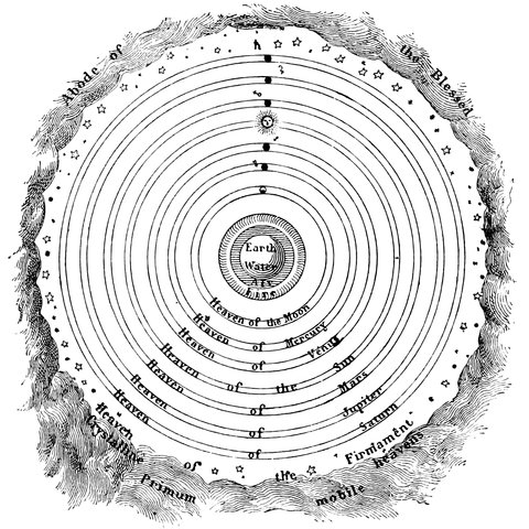
Fig. 1.—The Heavens according to Ptolemy.
4We begin with man’s first feeble efforts, the work which man was enabled to do by his unaided eye; and we end with the tremendous addition which he got to his observing powers by the invention of the telescope.
The first instrument used for astronomical observations was none of man’s making. In the old time the only instrument was the horizon; and, truth to tell, in a land of extended plains and isolated hills, it was not a bad one. Hence it was, doubtless, that observations in the first instance were limited to certain occurrences such as the risings and settings of the stars and the relative apparent distances of the heavenly bodies from each other.
So far as we are able to learn from ancient authors, the observations next added were those of the conjunctions of the planets and of eclipses. The Egyptians are stated to have recorded 373 solar, and 832 lunar eclipses; and this statement is probably correct, as the proportions are exact, and there should be the above number of each in from 1,200 to 1,300 years.
The Chinese also record an observation, made between the years 2514 and 2436 B.C., of five planets being in conjunction.
The Chaldeans appear to have observed the motions of the moon, and an observation in 2227 B.C. is recorded; but these old dates are probably fictitious.
It is impossible to regard without surprise the general attention given to astronomical investigation in those early days compared with what we find now. Yet if we attempt to build up for ourselves any idea as to the problems of which the ancients attempted the solution, it is difficult if not impossible to do it; we cannot realize the blank which the heavens presented 5to them, so many great men have lived between their time and our own, by whose labours we, even if unconsciously, have profited. The first idea seems to have been to observe which stars were rising or setting at seed or harvest time, to divide the heavens into Moon Stations, and then to mark astronomically their monthly and yearly festivals.
If one looks into the old records we find that all the labours of man which had to be performed in the country or elsewhere were determined, by the rising or setting of the stars. All the exertions of the navigator and the agriculturist were thus regulated. Of the planets in those early times we hear little, except from the Chinese annals which record conjunctions.
This was before man began to use the sun as a standpoint, and hence it is that there are so many references in the ancient writers to the rising and setting of the most striking star cluster—the Pleiades, and the most striking constellation—Orion. It is known that the year, in later times at all events, began in Egypt when the brightest star in the heavens, Sirius, the dog-star, rose with the sun, this day being called the 1st of the month Thoth,[1] which was the commencement of the Sothiac period of 1461 years.
It would appear that observations of culminations, that is, of the highest points reached by the stars, were not made till long after horizon observations were in full vigour; and here it is a question whether pyramids and the like were not the first astronomical instruments constructed by man, because for great nicety in such observations—a nicety, let us say, sufficient to determine astronomically by means of culminations the time for 6holding a festival—a fixed instrument of some kind was essential. The rich mine recently opened up by Mr. Haliburton and Mr. Ernest de Bunsen concerning the survival in all nations—in our own one takes the name the Feast of All Souls’—of ancient festivals governed by the midnight culmination of the Pleiades will doubtless ere long call general attention to this earliest form of accurate astronomical observation, and the determination by Professor Piazzi Smyth of the fact that in 2170 B.C., when the Pleiades culminated at midnight at the vernal equinox, the passages in the north and south faces of the pyramid of Gizeh were directed, the southern one to this culmination, and the northern one to the then pole star, α Draconis, at its transit, about 4° from the pole.
Hence one may regard the pyramid as the next astronomical
instrument to the horizon. While then it is
possible that such culmination observations soon replaced
in some measure that class of observations which heretofore
had been made on the horizon, another teaching
of horizon observations became apparent. By and by
travellers observed that as they travelled northwards the
stars that were just visible on the southern horizon, when
culminating, gradually disappeared below it. These observations
were at once seized on, and Anaximander
accounted for them by supposing that the earth was a
cylinder.[2] The idea of a sphere did not come till later;
when it did come then came the circle as an astronomical
instrument. For let us consider that a person
on the earth stands, say, at the equator; then he will
just be able to see along his north and south horizon
the stars pointed to by the axis of the globe: if now
he is transported northwards, his horizon will change
7with him; he will no longer be able to see the southern
stars, but the northern ones will gradually rise above his
horizon till he gets to the north pole, when the north
pole star, instead of being on his horizon, as was the case
when he was at the equator, will be over his head. So
by moving from the equator to the pole (or a quarter of
the distance round the earth) the stars have moved from
the horizon to the point overhead, or the zenith, that
is also a quarter of a circle. So it appears that if an
observer moves to such a distance that the stars appear
to move over a certain division of a circle with reference
to the horizon, he must have moved over an equal
division on the earth’s surface. Then, as now, the circle
in the Western world was divided into 360°, so that the
observer in moving 1° by the stars would have moved
over 1
360 of the distance round the earth, on the assumption
that the earth is a globe; and if the distance over
which the observer has moved be multiplied by 360,
the result will be the distance round the earth.
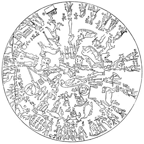
Fig. 2.—The Zodiac of Denderah.
8Now let us see how Posidonius a long time afterwards
(he was born about 135 years B.C.) applied this conception.
He observed that at Rhodes the star Canopus
grazed the horizon at culmination, while at Alexandria
it rose above it 7½°. Now 7½° is 1
48 of the whole circle;
so he found that from the latitude of Rhodes to that
of Alexandria was 1
48 of the circumference of the earth.
He then estimated the distance, getting 5,000 stadia as
the result; and this multiplied by 48 gave him 240,000
stadia, his measure of the circumference of the earth.
When the sun’s yearly course in the heavens had been determined, it was found that it was restricted to that band of stars called the Zodiac, Fig. 2; the sun’s position in the zodiac at any one time of the year being found by the midnight culmination of the stars opposite the sun; this and the apparent and heliacal risings and settings were alone the subjects of observation.
It is obvious, then, that when observations of this nature had gone on for some time, men would be anxious to map the stars, to make a chart of the field of heaven; and such a work was produced by Autolycus three and a half centuries before Christ. We also owe to Autolycus and Euclid, who flourished about the same time (300 B.C.), the first geometrical conceptions connected with the apparent motions of the stars.
9In the theorems of Autolycus there is a particular reference to the twelve parts of the zodiac, as denoted by constellations. The following are the most important propositions which he lays down:—
1. “The zodiacal sign occupied by the sun neither rises nor sets, but is either concealed by the earth or lost in the sun’s rays. The opposite sign neither rises nor sets, i.e., visibly, i.e., after sundown, but it is visible during the whole night.
2. “Of the twelve signs of the zodiac, that which precedes the sign occupied by the sun rises visibly in the morning; that which succeeds the same sign sets visibly in the evening.
3. “Eleven signs of the zodiac are seen every night. Six signs are visible, and the five others, not occupied by the sun, afterwards rise.
4. “Every star has an interval of five months between its morning and its evening rising, during which time it is visible. It has an interval of at least thirty days—between its evening setting, and its morning rising—during which time it is invisible.” (That is, the space passed over by the sun in its annual path is such that a star which you see on one side of the sun, when the sun rises at one time, would be seen a month afterwards on the other side of the sun.)
Autolycus makes no mention of the planets. Their irregular movements rendered them unsuited to the practical object which he had in view. He is, however, stated by Simplicius, as quoted by Sir G. C. Lewis to have proposed some hypothesis for explaining their anomalous motions, and to have failed in his attempt.
Euclid carries the results arrived at in this early pre-telescopic age much further; in a little-known treatise, the Phenomena,[3] he thus sums up the knowledge then acquired:—
10“The fixed stars rise at the same point, and set at the same point; the same stars always rise together, and set together, and in their course from the east to the west they always preserve the same distance from one another. Now, as these appearances are only consistent with a circular movement, when the eye of the observer is equally distant from the circumference of the circle in every direction (as has been demonstrated in the treatise on Optics), it follows that the stars move in a circle and are attached to a single body, and that the vision is equally distant from the circumference.
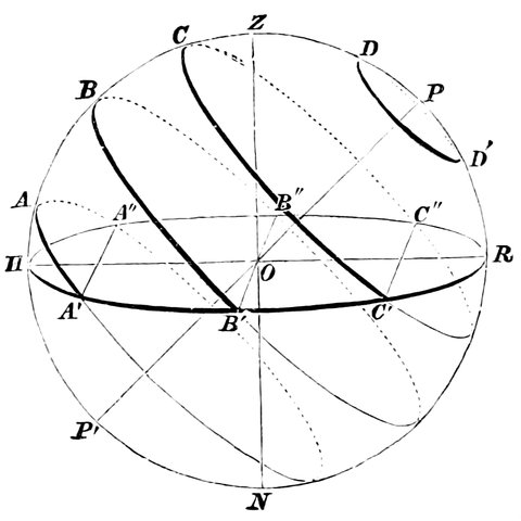
Fig. 3.—Illustration of Euclid’s statements. P the star between the Bears. D D´ the region of the always visible. C B A the regions of the stars which rise and set.
“A star is visible between the Bears, not changing its place, but always revolving upon itself. Since this star appears to be equally distant from every part of the circumference of each circle described by the other stars, it must be assumed that all the circles are parallel, so that all the fixed stars move along parallel circles, having this star as their common pole.
“Some of these neither rise nor set, on account of their moving in elevated circles, which are called the ‘always visible.’ They are the stars which extend from the visible pole to the Arctic circle. Those which are nearest the pole describe the smallest 11circle, and those upon the Arctic circle the largest. The latter appears to graze the horizon.
“The stars to the south of this circle all rise and set, on account of their circles being partly above and partly below the earth. The segments above the earth are large and the segments below the earth are small in proportion as they approach the Arctic circle, because the motion of the stars nearest the circle above the earth is made in the longest time, and of those below the earth in the shortest. In proportion as the stars recede from this circle, their motion above the earth is made in less time, and that below the earth in greater. Those that are nearest the south are the least time above the earth, and the longest below it. The stars which are upon the middle circle make their times above and below the earth equal; whence this circle is called the Equinoctial. Those which are upon circles equally distant from the equinoctial make the alternate segments in equal times. For example, those above the earth to the north correspond with those below the earth to the south; and those above the earth to the south correspond with those below the earth to the north. The joint times of all the circles above and below the earth are equal. The circle of the milky way and the zodiacal circle being oblique to the parallel circles, and cutting each other, always have a semicircle above the earth.
“Hence it follows that the heaven is spherical. For if it were cylindrical or conical, the stars upon the oblique circles, which cut the equator, would not in the revolution of the heaven always appear to be divided into semicircles; but the visible segment would sometimes be greater and sometimes less than a semicircle. For if a cone or a cylinder were cut by a plane not parallel to the base, the section is that of an acute-angled cone, which resembles a shield (an ellipse). It is, therefore, evident that if a figure of this description is cut in the middle both in length and breath, its segments will be unequal. But the appearances of the heaven agree with none of these results. Therefore the heaven must be supposed to be spherical, and to revolve equally round an axis of which one pole above the earth is visible and the other below the earth is invisible.
12“The Horizon is the plane reaching from our station to the heaven, and bounding the hemisphere visible above the earth. It is a circle; for if a sphere be cut by a plane the section is a circle.
“The Meridian is a circle passing through the poles of the sphere, and at right angles to the horizon.
“The Tropics are circles which touch the zodiacal circle, and have the same poles as the sphere. The zodiacal and the equinoctial are both great circles, for they bisect one another. For the beginning of Aries and the beginning of the Claws (or Scorpio) are upon the same diameter; and when they are both upon the equinoctial, they rise and set in conjunction, having between their beginnings six of the twelve signs and two semicircles of the equinoctial; inasmuch as each beginning, being upon the equinoctial, performs its movement above and below the earth in equal times. If a sphere revolves equally round its axis, all the points on its surface pass through similar axes of the parallel circles in equal times. Therefore these signs pass through equal axes of the equinoctial, one above and the other below the earth; consequently the axes are equal, and each is a semicircle; for the circuit from east to east and from west to west is an entire circle. Consequently the zodiacal and equinoctial circles bisect one another; each will be a great circle. Therefore the zodiacal and equinoctial are great circles. The horizon is likewise a great circle; for it bisects the zodiacal and equinoctial, both great circles. For it always has six of the twelve signs above the earth, as well as a semicircle of the equator. The stars above the horizon which rise and set together reappear in equal times, some moving from east to west, and some from west to east.”
We have given this long extract in justice to the men of old, containing as it does many of those geometrical principles which all our modern instruments must and actually do fulfil.
It is true that the present idea of the earth’s place in the system is different. Euclid imagined the earth to be 13at the centre of the universe. It is now known that the earth is one of various planets which revolve round the sun, and further, that the journey of the earth round the sun is so even and beautifully regulated that its motion is confined to a single plane. Year after year the earth goes on revolving round the sun, never departing, except to a very small extent, from this plane, which is one of the fundamental planes of the astronomer and called the Plane of the Ecliptic.
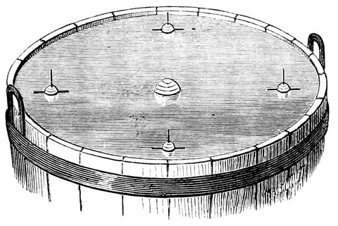
Fig. 4.—The Plane of the Ecliptic.
Suppose this plane to be a tangible thing, like the surface of an infinite ocean, the sun will occupy a certain position in this infinite ocean, and the earth will travel round it every year.
If the axis of the earth were upright, one would represent the position of things by holding a globe with its axis upright, so that the equator of the earth is in every part of its revolution on a level with this ecliptic sea. But it is known that the earth, instead of floating, as it were, upright, as in Fig. 4, has its axis inclined to the plane of the ecliptic, as in Fig. 5.
It is also known that by turning a globe round, distant objects would appear to move round an observer on the globe in an opposite direction to his own motion, 14and these distant objects would describe circles round a line joining the places pointed to by the poles of the earth, i.e., round the earth’s axis.
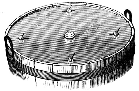
Fig. 5.—The Plane of the Ecliptic, showing the Inclination of the Earth’s Axis.
It is now easy to explain the observations referred to by Euclid by supposing the surface of the water in the tub to represent the plane of the ecliptic, that is, the plane of the path which the sun apparently takes in going round the earth; and examining the relative positions of the sun and earth represented by two floating balls, the latter having a wire through it inclined to the upright position; it will be seen at once by turning the ball on the wire as an axis to represent the diurnal motion of our earth, how Euclid finds the Bear which never sets, being the place in the heavens pointed to by the earth’s pole; and how all the stars in different portions of the heavens appear to move in complete circles round the pole-star when they do not set, and in parts of circles when they pass below the horizon. By moving the ball representing the earth round the sun and so examining their relative positions, during the course of a year it will be seen how the sun appears to travel through all the signs of the zodiac in succession 15in his yearly course, remaining a longer or shorter time above the horizon at different times of the year.
For it will be seen that if the spectator on the globe, when in the position that its inclined axis, as shown in Fig. 5, points towards the sun, were looking at the sun from a place where one can imagine England to be at midday, the sun would appear to be very high up above the horizon; and if he looked at it from the earth in the opposite part of its orbit it would be very low and near the horizon. When the earth, therefore, occupied the intermediate positions, the sun would be half way between the extreme upper position and the extreme lower position as the earth moves round the sun, and in this way the solstices, equinoxes, and the seasonal changes on the surface of our planet, are easily explained.
1. Corresponding to 20th July, 139 B.C.
2. Anaximander flourished about 547 B.C.
3. Quoted by Sir G. C. Lewis in his Astronomy of the Ancients, p. 187.
The ancients called the places occupied by the sun when highest and lowest the Solstices, and the intermediate positions the Equinoxes. The first instrument made was for the determination of the sun’s altitude in order to fix the solstices. This instrument was called the Gnomon. It consisted of an upright rod, sharp at the end and raised perpendicularly on a horizontal plane, and its shadow could be measured in the plane of the meridian by a north and south line on the ground. Whenever the shadow was longest the sun was naturally lowest down at the winter solstice, and vice versâ for the summer solstice.
Here then we leave observations on the horizon and come to those made on the meridian.
The Gnomon is said to have been known to the Chinese in the time of the Emperor Yao’s reign (2300 B.C.), but it was not used by the Greeks[4] till the time of 17Thales, about 585 B.C., who fixed the dates of the solstices and equinoxes, and the length of the tropical year—that is, the time taken by the sun to travel from the vernal equinoctial point round to the same point again.
The next problem was to discover the inclination of the ecliptic, or, what is the same thing, the amount that the earth’s equator is inclined to the ecliptic plane (represented by the surface of the water in our tub).
Now in order to ascertain this, the angular distance between the positions occupied by the sun when at the solstices must be measured; or, since one solstice is just as much below the equinoctial line as the other is above it, we might take half the angle between the solstices as being the obliquity required.
The first method of measuring the angle was to
measure the length of the sun’s shadow at each solstice,
and so, by comparison of the length of the
shadow with the height of the gnomon, calculate the
difference in altitude, the half of which was the angle
sought. And this was probably the method of the
Chinese, who obtained a result of 23° 38´ 11˝ in the
time of Yao; and also of Anaximander in his early
days, who obtained a result of 24°. But before trigonometrical
tables, the first of which seem to have been
constructed by Hipparchus and Ptolemy, were known,
in order to find this angle it was constructed geometrically,
and then what aliquot part of the circumference
it was, or how much of the circumference it contained
was determined; for the division of the circle into 360°
is subsequent to the first beginning of astronomy—and
hence it was that Eratosthenes said that the distance
18from the tropics was 11
83 of the circumference, and not
that it was 47° 46´ 26˝.
The gnomon is, without exception, of all instruments the one with which the ancients were able to make the best observations of the sun’s altitude. But they did not give sufficient attention to it to enable it to be used with accuracy. The shadow projected by a point when the sun is shining is not well defined, so that they could not be quite certain of its extremity, and it would seem that the ancient observations of the height of the sun made in this manner ought to be corrected by about half the apparent diameter of the sun; for it is probable that the ancients took the strong shadow for the true shadow; and so they had only the height of the upper part of the sun and not that of the centre. There is no proof that they did not make this correction, at least in the later observations.
In order to obviate this inconvenience, they subsequently terminated the gnomon by a bowl or disc, the centre of which answered to the summit; so that, taking the centre of the shadow of this bowl, they had the height of the centre of the sun. Such was the form of the one that Manlius the mathematician erected at Rome under the auspices of Augustus.
But in comparatively modern times astronomers have remedied this defect in a still more happy manner, by using a vertical or horizontal plate pierced with a circular hole which allows the rays of the sun to enter into a dark place, and in fact to form a true image of the sun on a floor or other convenient receptacle, as we find is the case in many continental churches.
Of course at this early period the reference of any 19particular phenomenon to true time was out of the question. The ancients at the period we are considering used twelve hours to represent a day, irrespective of the time of the year—the day always being reckoned as the time between sunrise and sunset. So that in summer the hours were long and in winter they were short. The idea of equal hours did not occur to them till later; but no observations are closer than an hour, and the smallest division of space of which they took notice was something like equal to a quarter or half of the moon’s diameter.
When we come down, however, to three centuries before Christ, we find that a different state of things is coming about. The magnificent museum at Alexandria was beginning to be built, and astronomical observations were among the most important things to be done in that vast establishment. The first astronomical workers there seem to have been Timocharis and Aristillus, who began about 295 B.C., and worked for twenty-six years. We are told that they made a catalogue of stars, giving their positions with reference to the sun’s path or ecliptic.
It was soon after this that the gnomon gave way to
the invention of the Scarphie. It is really a little
gnomon on the summit of which is a spherical segment.
An arc of a circle passing out of the foot of the style
was divided into parts, and we thus had the angle which
the solar ray formed with the vertical. Nevertheless
the scarphie was subject to the same inconveniences, and
it required the same corrections, as the gnomon; in short,
it was less accurate than it. That did not, however,
hinder Eratosthenes from making use of it to measure
the size of the earth and the inclination of the ecliptic
20to the equator. The method Eratosthenes followed in
ascertaining the size of the earth was to measure the
arc between Syene and Alexandria by observing the
altitude of the sun at each place. He found it to be
1
50 of the circumference and 5,000 stadia, so that if 1
50
of the circumference of the earth is 5,000 stadia, the
whole circumference must be 50 times 5,000, or 250,000
stadia.[5]
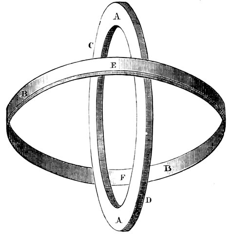
Fig. 6.—The First Meridian Circle.
And now still another instrument is introduced, and we begin to find the horizon altogether disregarded in favour of observations made on the meridian.
The instrument in question was probably the invention of Eratosthenes. It consisted of two circles of nearly the same size crossing each other at right angles, (Fig. 6); one circle represented the equator and the other the meridian, and it was employed as follows:—
The circle A was fixed perfectly upright in the 21meridian, so that the greatest altitude of the sun each day could be observed; the circle B was then placed exactly in the plane of the earth’s equator by adjusting the line joining C and D to the part of the heavens between the Bears, about which the stars appear to revolve. This done, the occurrence of the equinox was waited for, at which time the shadow of the part of the circle E must fall upon the part marked F, so as exactly to cover it.
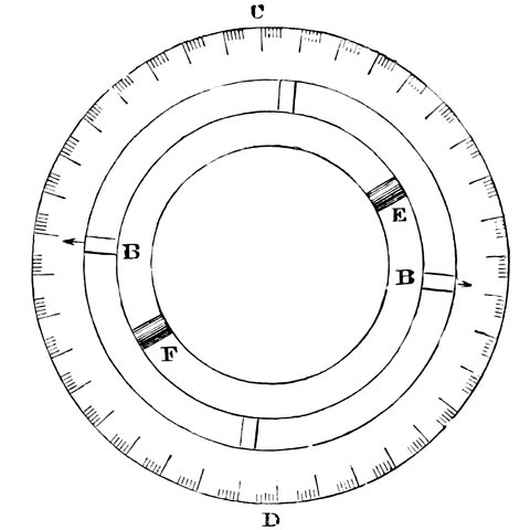
Fig. 7.—The First Instrument Graduated into 360° (West Side).
We now come to the time when the circle began to be divided into 360 divisions or degrees—about the time of Hipparchus (160 B.C.). There are two instruments described by Ptolemy for measuring the altitude of the sun in degrees instead of in fractions of a circle. They, like the gnomon, were used for determining the altitude of the sun. The first, Fig. 7, consisted of two circles of copper, one, C D, larger than the other, 22having the smaller one, B, so fitted inside it as to turn round while the larger remained fixed. The larger was divided into 360°, and the smaller one carried two pointers. This instrument was placed perfectly upright and in the plane of the meridian, and with a fixed point, C, always at the top by means of a plumb-line hanging from C over a mark, D. On this small circle are two square knobs projecting on the side, E and F. When the sun was on the meridian the small circle was turned so as to bring the shadow of the knob E over the knob F, and then the degree to which the pointer pointed was read off on the larger circle. And of course, as the position of the knobs had to be changed as the sun moved in altitude, the angle through which the sun moved was measured, and the circle being fixed, the sun’s altitude could always be obtained.
The other instrument consisted of a block of wood or stone, one side of which was placed in the plane of the meridian; and on the top corner of this side was fixed a stud; and round it as a centre a quarter of a circle was described, divided into 90°. Below this stud was another, and by means of a plumb-line one stud could always be brought over the other; so that the instrument could always be placed in a true position. At midday then, when the sun was shining, the shadow of the upper stud would fall across the scale of degrees, and at once give the altitude of the sun.
Ptolemy, who used this instrument, found that the arc included between the tropics was 47⅔°.
The result of all these accurate determinations of the solstices and equinoxes was the fixing of the length of the year.
23We have so far dealt with the methods of observation which depend upon the use of the horizon and of the meridian; we will now turn our attention to extra-meridional observations, or those made in any part of the sky.
Before we discuss them, let us consider the principles on which we depend for fixing the position of a place on a globe. On a terrestrial globe there are lines drawn from pole to pole, called meridians of longitude; and if a place is on any one meridian it is said to be in so many degrees of longitude, east or west of a certain fixed meridian, as there are degrees intercepted between this meridian and the one on which the place is situated. There are also circles at right angles to the above and parallel to the equator; these are circles of latitude, and a place is said to have so many degrees N. or S. latitude as the circle which passes through it intercepts on a meridian between itself and the equator, so that the latitude of a place is its angular distance from the equator, and the longitude is its angular distance E. or W. of a fixed meridian—that of Greenwich being the one used for English calculation; and each large country takes the meridian of its central observatory for its starting-point. The distance round the equator is sometimes expressed in hours instead of degrees; for as the earth turns round in twenty-four hours, so the equator can be divided into hours, minutes, and seconds. So that if a star be just over the meridian of Greenwich, which is 0° 0´ 0˝, or 0h 0m 0s longitude at a certain time, in an hour after it will be over a meridian 15° or one hour west of Greenwich, and so on, till at the end of twenty-four hours it would be over Greenwich again.
Now let us turn to the celestial globe.
24What we call latitude and longitude on a terrestrial globe is called declination and right ascension on the celestial globe, because in the heavens there is a latitude and longitude which does not correspond to our latitude and longitude on the earth. If we imagine the lines of latitude and longitude on the earth to be projected, say as shadows thrown on the heavens by a light in the centre of the earth, the lines of right ascension (generally written R.A.) and declination (written Dec. or D.) will be perfectly depicted.
But there is another method of co-ordinating the stars, in which we have the words latitude and longitude used also, as we have said, for the heavens; meaning the distance of a star from the ecliptic instead of the equator, and its distance east or west measured by meridians at right angles to the ecliptic.
This premised, we are in a position to see the enormous advance rendered possible by the methods of observation introduced by Hipparchus and Ptolemy.
4. This instrument is also reported to have been used by the Chaldeans in 850 B.C.; the invention of it being attributed to Anaximander. This philosopher, says Diogenes Laertes, observed the revolution of the sun, that is to say, the solstices, with a gnomon; and probably he measured the obliquity of the ecliptic to the equator, which his master had already discovered.
5. 28,279 miles.
Among the astronomers of antiquity there are two figures who stand out in full relief—Hipparchus and Ptolemy. The former, “the father of astronomy,” is especially the father of instrumental astronomy. As he was the first to place observation on a sure basis, and left behind him the germs of many of our modern instruments and methods, it is desirable to refer somewhat at length to his work and that of his successor, Ptolemy.
Hipparchus introduced extra-meridional observations. He followed Meton, Anaximander, and others in observing on the meridian instead of on the horizon, and then it struck him that it was not necessary to keep to the meridian, and he conceived an instrument, called an Astrolabe, fixed on an axis so that the axis would point to the pole-star, like the one represented in Fig. 8. This engraving is of one of Tycho Brahe’s instruments, which is similar to but more elaborate than that of Hipparchus no drawing of which is extant. C, D, is the axis of the instrument pointed to the pole of the heavens; E, B, C, the circle placed North and South representing the meridian; R, Q, N, the circle placed at right angles 26to the polar axis, representing the equator, but in the instrument of Hipparchus it was fixed to the circle E, B, C, and not movable in its own plane as this one is. M, L, K, is a circle at right angles to the equator, and moving round the poles, being a sort of movable meridian. Thus, then, if the altitude of a star from the equator (or its declination) was required to be observed, the circle was turned round on the axis, and the sights, Q, M, moved on the circle till they, together with the sight A, pointed to the star; the number of degrees between one of the sights and the equator, was then read off, giving the declination required. The number of degrees, or hours and minutes, of Right Ascension, from K to E could be then read off along the circle R, Q, N, giving the distance of the object from the meridian. As the stars have an apparent motion, the difference in right ascension between two stars only could be obtained by observing them directly after each other, and allowing for the motion during the interval between the two observations.
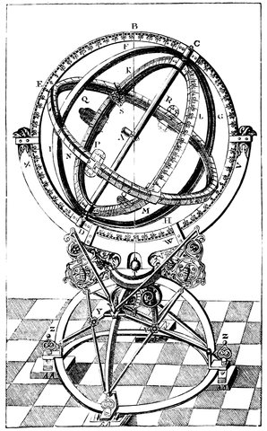
Fig. 8.—Astrolabe (Armillæ Æquatoriæ of Tycho Brahe) similar to the one contrived by Hipparchus.
27In this manner, then, Hipparchus could point to any part of the heavens and observe, on either side of the meridian, the sun, moon, planets or any of the stars, and obtain their distance from the equatorial plane; but another fixed plane was required; and Hipparchus, no longer content with being limited to measuring distances from the equator, thought it might be possible to get another starting-point for distances along the equator. It was the determination of this plane, or starting-point from which to reckon right ascension, that was one of the difficulties Hipparchus had to encounter. This point he decided should be the place in the heavens where the sun crosses the equator at the spring equinox. But the stars could not be seen when the sun was shining; how, then, was he to fix that point so that he could measure from it at night?
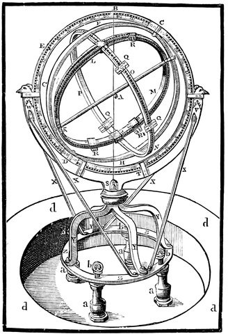
Fig. 9.—Ecliptic Astrolabe (the Armillæ Zodiacales of Tycho Brahe), similar to the one used by Hipparchus.
He found it at first a tremendous problem, and at last hit upon this happy way of solving it. He reasoned in this way: “As an eclipse of the moon is caused by the earth’s shadow being thrown by the sun on the moon, if this happen near the equinox, the sun and moon must then be very near the equator, and very near the ecliptic—in fact, near the intersection of the two fundamental planes which are supposed to cross each other. If I can observe the distance, measured along the equator, between the moon and a star, I shall have obtained the star’s actual place, because, of course, if the moon is exactly opposite the sun, the sun will be 180 degrees of right ascension from the moon, and the right ascension of the sun being known it will give me the position of the star.” This method of observation was an extremely good one for the time, but it could only have been used during an eclipse of the moon, and when the sun was so near the equator that its distance from the equinoctial point along the ecliptic, as calculated by the time elapsed since the equinox, 29differed little from the same distance measured along the equator, or its right ascension, so that the right ascension of the sun was very nearly correct. Hipparchus hit upon a very happy alteration of the same instrument to enable him to measure latitude and longitude instead of declination and right ascension—in fact, to measure along the ecliptic instead of the equator. Instead of having the axis of the inner rings parallel to the axis of the earth, as in Fig. 9, he so arranged matters that the axis of this system was separated from the earth’s axis to the extent of the obliquity of the ecliptic, the circle R, Q, N, therefore instead of being in the plane of the equator, was in that of the ecliptic. Then it was plain to Hipparchus that he would, instead of being limited to observe during eclipses of the moon, be able to reckon from the sun at all times; because the sun moves always along the ecliptic and the latitude of the sun is nothing.
We will now describe the details of the instrument. There is first a large circle, E, B, C, Fig. 9 (which is taken from a drawing of this kind of instrument as constructed subsequently by Tycho Brahe), fixed in the plane of the meridian, having its poles, D, C, pointing to the poles of the heavens; inside this there is another circle, F, I, H, turning on the pivots D, C, and carrying fixed to it the circle, O, P, arranged in a plane at right angles to the points I, K, which are placed at a distance from C and D equal to the obliquity of the ecliptic; so that I and K represent the poles of the ecliptic, and the circle, O, P, the ecliptic itself. There is then another circle, R, M, turning on the pivots I and K, representing a meridian of latitude, and along which it is measured.
Then, as the sun is on that part of the ecliptic 30nearest the north pole, in summer, its position is represented by the point F on the ecliptic, and by N at the winter solstice; so, knowing the time of the year, the sight Q can be placed the same number of degrees from F as the sun is from the solstice, or in a similar position on the circle O P as the sun occupies on the ecliptic.
The circle can then be turned round the axis C, D, till the sight Q, and the sight opposite to it, Q´, are in line with the sun. The circle, O, R, will then be in the plane of the ecliptic, or of the path of the earth round the sun. The circle, R, M, is then turned on its axis, I, K, and the sights, R, R, moved until they point to the moon. The distance Q, L, measured along O, P, will then be the difference in longitude of the moon and sun, and its latitude, L, R, measured along the circle R, M.
But why should he use the moon? His object was to determine the longitude of the stars, but his only method was to refer to the motion of the sun, which could be laid down in tables, so that its longitude or distance from the vernal equinox was always known. But we do not see the stars and the sun at the same time; therefore in the day time, while the moon was above the horizon, he determined the difference of longitude between the sun and the moon, the longitude of the sun or its distance from the vernal equinox being known by the time of the year; and after the sun had set he determined the difference of longitude between the moon and any particular star; and so he got a fair representation of the longitude of the stars, and succeeded in tabulating the position of 1,022 of them.
31It is to the use of this instrument that we owe the discovery of the precession of the equinoxes.
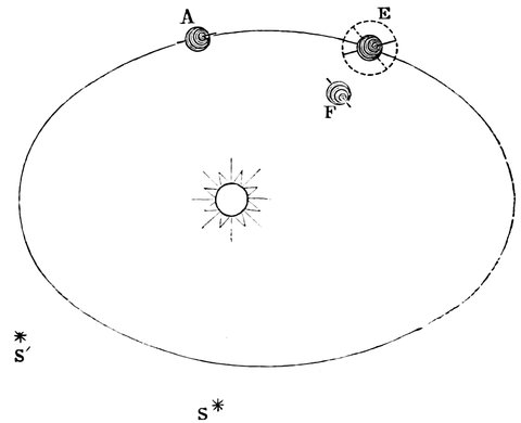
Fig. 10.—Diagram Illustrating the Precession of the Equinoxes.
After Hipparchus had fixed the position of a number of stars, he found that on comparing the place amongst them of the sun at the equinoxes in his day with its place in the time of Aristillus that the positions differed—that the sun got to the equinox, or point where it crossed the equator, a short time before it got to the place amongst the stars where it crossed in the time of Aristillus; in fact, he found that the equinoctial points retrograded along the equator, and Ptolemy (B.C. 135) appears to have established the fact that the whole heavens had a slow motion of one degree in a century which accounted for the motion of the equinoxes.
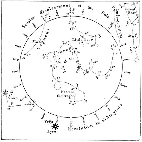
Fig. 11.—Revolution of the Pole of the Equator round the Pole of the Ecliptic caused by the Precession of the Equinoxes.
Let us see what we have learned from the observation of this motion, for motion there is, and the ancients must be looked on with reverence for their skill in determining it with their comparatively rude instruments. In Fig. 10, A represents the earth at the vernal equinox, and at this time the sun appears near a certain star, S, which was fixed by Aristillus; but in the time of Hipparchus the equinox happened when the sun was near a star, S´, and before it got to S. Now we know that the sun has no motion round the earth, and that the equinox simply depends on the position of the earth’s equator in reference to the ecliptic; so that in order to produce the equinox when the earth is at E and before it get to A, its usual place, all we have to do is to turn the pole of the earth through a small arc of the dotted 33circle, and so alter its position to that shown at F, when its equator and poles will have the same position as regards the sun as they have at A, so the equinox will happen when the earth is at E, and before it reaches A. This may be practically represented by taking an orange and putting a knitting-needle through it, and drawing a line representing the equator round it, and half immersing it in a tub of water, the surface of which represents the ecliptic. We are then able to examine these motions by moving the orange round the tub to represent the earth’s annual motion, and at the same time making the orange slowly whobble like a spinning-top just before it falls, by moving the top of the knitting-needle through a small arc of a circle in the same direction as the hands of a clock at every revolution of the orange round the centre of the tub.
The points where the equator is cut by the surface of the water (or ecliptic) will then change, as the orange whobbles, and the line joining them, will rotate, and as the equinox happens when this line passes through the sun, it will be seen that this will take place earlier at each revolution of the orange round the tub.
The equinox will therefore appear to happen earlier each year, so that the tropical year, or the time from equinox to equinox, is a little shorter than the sidereal year, or the time that the earth takes to travel from a certain place in its orbit to the same again; for if the earth start from an equinoctial point, the equinox will happen before it gets to the same place where the equinoctial point was at starting.
This is called the precession of the equinoxes.
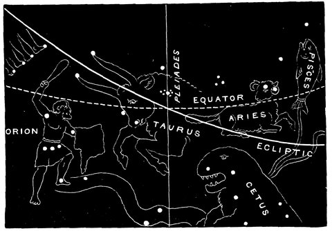
Fig. 12.—The Vernal Equinox among the Constellations, B.C. 2170.
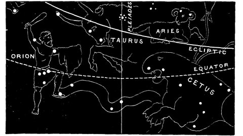
Fig. 13.—Showing how the Vernal Equinox has now passed from Taurus and Aries.
This discovery must be regarded as the greatest triumph obtained by the early stargazers, and there is much evidence to show that when the zodiac was first marked out among the central zone of stars, the Bull and not the Ram was the first of the train. Even the Ram, owing to precession, is no longer the leader, for the sign Aries is now in the constellation Pisces. The two accompanying drawings by Professor Piazzi Smyth of the position of the vernal equinox among the stars in the years 2170 B.C. and 1883 A.D. will show how precession has brought about celestial changes which have 35not been unaccompanied by changes of religious ideas and observances in origin connected with the stars.
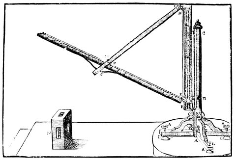
Fig. 14.—Instrument for Measuring Altitudes.
We now come to Ptolemy. There was another instrument used by Ptolemy, and described by him, which we may mention here; it was called the Parallactic Rules, so named perhaps because that ancient astronomer used it first for the observation of the parallax of the moon. It consists of three rods, D E, D F, E F, Fig. 14, two of which formed equal sides of an isosceles triangle; and the third, which had divisions on it, made the one at the base, or was the chord of the angle at the summit. One of the equal sides, D F, was furnished with pointers, over which a person observed the star, whilst the other, D E, was placed vertically, so that they read off the divisions on E F, and then, by means of a table of chords, the angle was found; this angle was the distance of the star from the zenith. Ptolemy, wishing to observe with great accuracy the position of the moon, made himself an 36instrument of this kind of a considerable size; for the equal rulers were four cubits long, so that its divisions might be more obvious. He rectified its position by means of a plumb-line. Purbach, Regiomontanus, and Walther, astronomers of the fifteenth century, employed this manner of observing, which, considering the youth of astronomy, was by no means to be despised. This instrument, constructed with great care, would have sufficiently been useful as far as concerns certain measurements and would have furnished results sufficiently exact; but the part of ancient astronomy that failed was the way of measuring time with any precision.
There were astronomers who proposed clepsydras for this purpose; but Ptolemy rejected them as very likely to introduce errors; and indeed this method is subject to much inconvenience and to irregularities difficult to prevent. However, as the measurement of time is the soul of astronomy, Ptolemy had recourse to another expedient which was very ingenious. It consisted in observing the height of the sun if it were day, or of a fixed star if it were night, at the instant of a phenomenon of which he wished to know the time of occurrence, for the place of the sun or star being known to some minutes of declination and right ascension as also was the latitude of the place, he was able to calculate the hour; thus when they observed, for example, an eclipse of the moon, it was only necessary to take care to get the height of some remarkable star at each phase of the eclipse, say at the commencement and at the end, in order to be able to conclude the true time at which it took place. This was the method adopted by astronomers until the introduction of the pendulum.
Leaving behind us the results of the researches of Ptolemy, who succeeded Hipparchus and whose methods have been described, and passing over the astronomy of the Arabs and Persians as being little in advance of Hipparchus and Ptolemy, we come down to the sixteenth century of our era.
Here we find ourselves in presence of the improvements in instruments effected by a man whose name is conspicuous—Tycho Brahe—a Danish nobleman who, in the year 1576, established a magnificent observatory at Huen, which may be looked upon as the next building of importance after that great edifice at Alexandria which has already been referred to.
What Hipparchus was to the astronomy of the Ancients such was Tycho to the astronomy of the Middle Ages. As such his life merits a brief notice before we proceed to his work. He was born at Knudsthorp, near Helsingborg, in Sweden, in 1546, and went to the University of Copenhagen to prepare to study law; while there he was so struck with the prediction of an eclipse of the sun by the astrological almanacks that he gave all his spare time to the study of astronomy. In 381565 his uncle died and Tycho Brahe fell into possession of one of his uncle’s estates; and as astronomy, or astrology as it was then called, was thought degrading to a man in his position by his friends, who took offence at his pursuits and made themselves very objectionable, he left for a short stay at Wittenberg, then he went to Rostock and afterwards to Augsburg, where he constructed his large quadrant. He returned to his old country in 1571; while there, Frederick II., King of Denmark, requested him to deliver a course of lectures on astronomy and astrology and became his most liberal patron. The King granted to Tycho Brahe for life the island of Huen, lying between Denmark and Sweden, and built there a magnificent observatory and apartments for Tycho, his assistants and servants. The main building was sixty feet square, with observing towers on the north and south, and a library and museum. Tycho called this Uraniberg—the city of the heavens; and he afterwards built a smaller observatory near called by him Sternberg—city of the stars, the former being insufficiently large to contain all his instruments.
The following is a list of these instruments as given in Sir David Brewster’s excellent memoir of Brahe, in Martyrs of Science:—
1. A semicircle of solid iron, covered with brass, four cubits radius.
2. A sextant of the same materials and size.
3. A quadrant of one and a half cubits radius, and an azimuth circle of three cubits.
4. Ptolemy’s parallactic rules, covered with brass, four cubits in the side.
5. Another sextant.
6. Another quadrant, like No. 3.
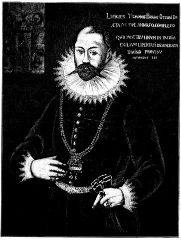
Fig. 15.—Portrait of Tycho Brahe (from original painting in the possession of Dr. Crompton, of Manchester).
417. Zodiacal armillaries of melted brass, and turned out of the solid, of three cubits in diameter.
Near this observatory there was a large clock with one wheel two cubits in diameter, and two smaller ones which, like it, indicated hours, minutes, and seconds.
8. An armillary sphere of brass, with a steel meridian, whose diameter was about four cubits.
9. Brass parallactic rules, which revolved in azimuth above a brass horizon, twelve feet in diameter.
10. A half sextant, of four cubits radius.
11. A steel sextant.
12. Another half sextant with steel limb, four cubits radius.
13. The parallactic rules of Copernicus.
14. Equatorial armillaries.
15. A quadrant of a solid plate of brass, five cubits in radius, showing every ten seconds.
16. In the museum was the large globe made at Augsburg.
17. In the central part, a large semicircle, with a brass limb, and three clocks, showing hours, minutes, and seconds.
18. Equatorial armillaries of seven cubits, with semi-armillaries of nine cubits.
19. A sextant of four cubits radius.
20. A geometrical square of iron, with an intercepted quadrant of five cubits, and divided into fifteen seconds.
21. A quadrant of four cubits radius, showing ten seconds, with an azimuth circle.
22. Zodiacal armillaries of brass, with steel meridians, three cubits in diameter.
23. A sextant of brass, kept together by screws, and capable of being taken to pieces for travelling with. Its radius was four cubits.
24. A movable armillary sphere, three cubits in diameter.
25. A quadrant of solid brass, one cubit radius, and divided into minutes by Nonian circles.
26. An astronomical radius of solid brass, three cubits long.
27. An astronomical ring of brass, a cubit in diameter.
28. A small brass astrolabe.
42Tycho Brahe carried on his work at Uraniberg for twenty-one years, and appears to have been visited by many of the princes of the period and by students anxious to learn from so great a man. In Frederick’s treatment of Tycho Brahe we have an early and munificent and, in its results, most successful instance of the endowment of research. On the death of Frederick II., in 1588, Christian IV. came to the throne. The successor cared little for astronomy, and his courtiers, who were jealous of Tycho’s position, so acted upon him that the pension, estate and canonry with which Tycho had been endowed were taken away. Unable to put up with these insults and loss of his money, he left for Wandesburg in 1597, where he was entertained by Count Henry Rantzau. It was now that he wrote and published the Astronomiæ instauratæ Mechanica, a copy of which, together with his catalogue of 1000 stars, was sent to the Emperor Rudolph II., who invited him to go to Prague. This he accepted, and he and his family went to the castle of Benach in 1599, and a pension of 3000 crowns was given to him. Ten years afterwards he removed with his instruments into Prague to a house purchased and presented to him by the Emperor; here he died in the same year.
The wonderful assistance which Tycho Brahe was able to bring to astronomy shows that then, as now, any considerable advance in physical investigation was more or less a matter of money, and whether that money be found by individuals or corporations, now or then, we cannot expect any considerable advance without such a necessary adjunct.
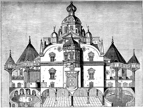
Fig. 16.—Tycho Brahe’s Observatory on the Island of Huen.
44The principal instruments used at first by Tycho Brahe resembled the Greek ones, except that they were much larger. Hipparchus was enabled to establish the position of a heavenly body within something less than one degree of space—some say within ten minutes; but there was an immense improvement made in this direction in the instruments used by Tycho.
One of the instruments which he used was in every way similar to the equatorial astrolabe designed, by Hipparchus, and was called by Tycho, the ‘armillæ equatoriæ’ (Fig. 8). With that instrument in connection with others Tycho was enabled to make an immense advance upon the work done by Hipparchus.
Tycho, like Hipparchus, having no clock, in the modern sense, was not able to determine the difference of time between the transit of the sun or a particular star over the meridian, so that he was compelled to refer everything to the sun at the instant of observation, and he did that by means of the moon. Hipparchus, as we have seen, determined the difference of longitude, or right ascension, between the sun and the moon and between the moon and the stars, in the manner already described, and so used the moon as a means of determining differences between the longitude or right ascension of the sun and the stars.
Now Tycho, using an instrument similar to that of Hipparchus, saw that he would make an improvement if instead of using the Moon he used Venus; for the measure of the surface of the moon was considerable, and could not be easily reckoned, and its apparent position in the heavens was dependent on the position of a person on the earth,—because it is so near the earth that it has a sensible parallax, that is, a person at the equator of the earth might see the moon in the direction of a certain star; but, on going to the pole, the moon would appear below 45the line of the star. If one were looking at a kite in the air to the south and then walked towards the south, the kite would gradually get over head, and on proceeding further it would get north. To persons at different stations the kite would appear in different positions, and the nearer the kite was to the observer the less distance he would have to go to make it change its place. So also with the moon; it is so near to us that a change of place on the earth makes a considerable difference in the direction in which it is seen. Instead, therefore, of using the Moon, Tycho used Venus, and so mapped 1,500 stars after determining their absolute right ascensions, in this manner without the use of clocks.
Fig. 8 shows the instrument called the “armillæ equatoriæ,” which he constructed, and which was based upon the principle of that which Hipparchus had used. Here the axis of motion, C, D, of these circles is so arranged that it is absolutely parallel to the axis of the earth; but instead of the circle R, Q, N, representing the equator, being fixed, it revolved in its own plane while held by the circle G, H, I, making its use probably more easy, but leaving the principles unaltered.
Tycho Brahe also used another similar instrument of much larger size for the same purposes as the one we have just considered. It consisted of a large circle, which was seven cubits in diameter, corresponding to the circle K, L, M, Fig. 8; and carrying the sights in the same manner, it was placed in a circular pit in the ground, with its diameter pointing towards the pole. This was used for measuring declinations. The circle R, Q, N, Fig. 9, was represented by a fixed circle carried on pillars surrounding the pit, and along which the right ascension of the star was measured. This instrument, 46therefore, was more simple than the smaller one, and probably much more accurate.
Tycho was not one of those who was aware of the true system of the universe; he thought the earth fixed, as Ptolemy and others did; but whether we suppose the earth to be movable in the middle of the vault of stars or stationary, in either case that position is absolutely immaterial in ascertaining the right ascension of stars. If one takes the terrestrial globe, and looks upon the meridians, it is at once clear that the distance from meridian to meridian remains unaltered, whether the globe is still or turning round: so the stars maintain their relative positions to each other, whether we consider the earth in motion or the sphere in which the stars are placed to revolve round it.
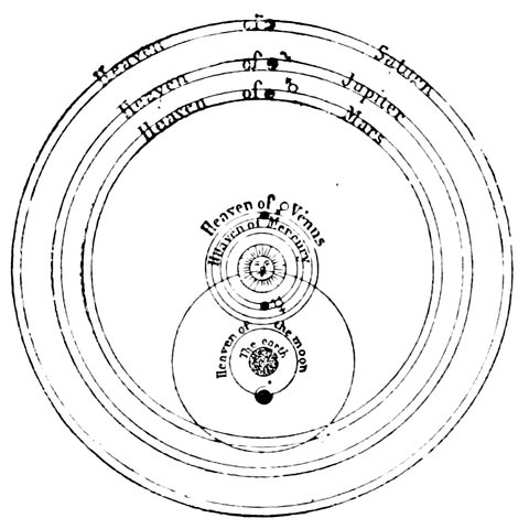
Fig. 17.—Tycho Brahe’s System.
The introduction of clocks gave Tycho the invention of the next instrument, which was the transit circle. At this time the pendulum had not been invented; but it struck him and others that there was no necessity for having two or more circles rotating about an axis parallel 47to the earth’s axis, as in the astrolabes or armillæ, but only to have one circle in the plane of the meridian of the place. So that, by the diurnal movement of the earth round its own axis, all the stars in the heavens would gradually and seriatim be brought to be visible along the arc of the circle, so he arranged matters in the following way.
The stars were observed through a hole in a wall and through an eyehole, sliding on a fixed arc. The number of degrees marked at the eyehole on the arc at once gave the altitude of the heavenly bodies as seen through that hole. If a star was very high, it would be necessary for an observer to place his eye low down to be able to see it. If it were near the horizon, he would have to travel up to the top of this circle to determine its altitude, and having done that, and knowing the latitude of the place of observation, the observer will be able to determine the position of the star with reference to the celestial equator. The actual moment at which the star was seen was noted by the clock, and the time that the sun had passed the hole being also previously noted, the length of time between the transits was known; and as the stars appear to transit or pass the meridian every twenty-four hours, it was at once known what part of the heavens was intercepted between the sun and the star in degrees, or, as is usually the case, the right ascension of the star was left expressed in hours and minutes instead of degrees; thus he had a means of determining the two co-ordinates of any celestial body.
The places of the comet of 1677, which Tycho discovered, and of many stars, were determined with absolute certainty; but astronomers began to be ambitious. It was necessary in using this instrument to wait till a 48celestial body got to the meridian. If it was missed, then they had to wait till the next day; and further, they had no opportunity whatever of observing bodies which set in the evening.
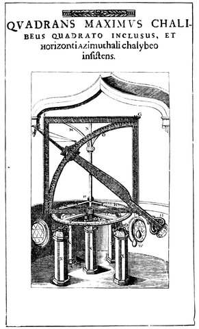
Fig. 18.—The Quadrans Maximus reproduced from Tycho’s plate.
Seeing, therefore, that clocks were improving, it was suggested by one of Tycho’s compeers, the Landgrave of Hesse-Cassel, that by an instrument arranged something like Fig. 18, it would be possible to determine the exact position of any body in the heavens when 49examined out of the meridian, and so they got again to extra-meridional observations.
The instrument used by Tycho Brahe for the purpose, called the Quadrans Maximus, is represented in Fig. 18. In this there is the quadrant B, D, one pointer being placed, as shown at the bottom, near H, and the other at the top, C. These pointers or sights were directed at the star by moving the arm C, H, on the pivot A, and turning the whole arm and divided arc round on the axis N, R. The altitude of the star is then read off on the quadrant B, D, and the azimuth, or number of degrees east or west of the north and south line, is then read off on the circle Q, R, S. The screws Y, Y, served to elevate the horizontal circle, and level it exactly with the horizon, and the plummets W and V, hanging from G, were to show when the circle was level or not; for the part A, G, being at right angles to the circle should be upright when the circle is level, so that if A, G, is upright in all positions when moved round the circle in azimuth, the circle is horizontal.
Here, then, is an instrument very different in principle from what we had before. In this case the heavens are viewed from the most general standpoint we can obtain—the horizon; but observations such as these refer to the position of the place of observation absolutely, without any reference to the position of the body with respect to the equator or the ecliptic; but knowing the latitude of the place of observation and the time, it was possible for a mathematical astronomer to reduce the co-ordinates to right ascension and declination, and so actually to look at the position of these bodies with reference to the celestial sphere.
Tycho also had various other instruments of the same kind, differing only in the position of the quadrant D, B, 50and of the circle on which the azimuth was measured. These instruments are the same in principle as our modern alt-azimuth, which will be described hereafter, one form having a telescope and the other being without it.
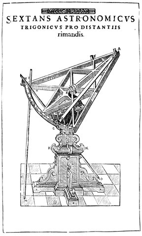
Fig. 19.—Tycho’s Sextant.
Fig. 19 is yet another very important instrument invented by Tycho Brahe; it is the prototype of our modern much used sextant. It was used by Tycho Brahe for 51determining the distance from one body to another in a direct line; a star or the moon, say, was observed by the pointers C, A, while another was observed by the pointers N, A, by another observer. The number of degrees then between N and C gave the angular distance of the two bodies observed. This instrument was mounted at E, so that it could be turned into any position. Not only then had this instrument its representative in our present sextant, but it was used in the same way, not requiring to be fixed in any one position. We also find represented in Tycho Brahe’s book another form of the same instrument, the sight A being next the observer, instead of away from him, so that he could observe the two stars through the sights N and C without moving the eye. In this form only one observer was required instead of two as in the last.
There was also another instrument, Fig. 6, used by this great astronomer, very similar to Ptolemy’s parallactic rules, used for measuring zenith distances, or the distances of stars from the part exactly overhead. The star or moon was observed by the sights H, I, and the angle from the upright standard D, K, given by divisions on the rod E, F, D, E being placed exactly upright by a plummet, and being also able to turn on hinges at B and C, any part of the sky could be reached. There is one more of his instruments that needs notice—he had so many of all kinds that space will not allow reference to more than a very few. This one was for measuring the altitudes of the stars as they passed the meridian; it is a more convenient form of the mural quadrant, and instead of a hole in the wall, there are sights on a movable arm, working over a divided quadrant fixed in the plane of the meridian, just like the quadrant outside the 52horizontal circle, so the observer had no reason to move up or down according as the star was high or low.
Here then ends the pre-telescopic age. Tycho was one of the very last of the distinguished astronomers who used instruments without the telescope. We began with the horizon, and we have now ended with the meridian. We also end with a power of determining the position of a heavenly body to ten seconds of space, the instrument of the Greeks reading to 10´ and those of Tycho to 10˝.
We began with the immovable earth fixed in the midst of the vault of the sky, and on this assumption Tycho Brahe made all his observations, which ended in enabling Kepler to give us the true system of the world, which was the requisite basis for the crowning triumph of Newton.
It is difficult to give the credit of the invention of the telescope to any one particular person, for, as in the case of most instruments, its history has been a history of improvements; and whether we should give the laurel to Jansen, Baptista Porta, Galileo or to others whose names are unknown, is an invidious task to decide; we will therefore not enter in any way into the question, interesting though it be, as to who was the inventor of the “optick tube,” as the telescope was called by its first users.
The telescope is not a thing in the ordinary sense—it is a combination of things, the things being certain kinds of lenses, concave and convex, known and used as spectacles long before they were combined to form the telescope.
The first telescopes depended on the refraction of light; others, to which attention will be called in a future chapter, depended on reflection.
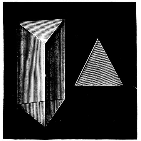
Fig. 20.—View and Section of a Prism.
In order to understand the action of a lens, it is necessary to understand the action of a prism. By the aid of Fig. 20 the action of the lenses of which telescopes are constructed will be understood. A prism is a piece of glass, or other transparent substance, the sides of which are so inclined to each other that its section is a triangle, and its action on light passing through it is to change the direction of the course of the beam. If we examine Fig. 21 we shall understand the action clearly. It is a known law, that when a beam of light falls obliquely on the surface of a medium more dense than that through which it has been passing, its direction is changed to a new one, nearer the line drawn at right angles to that surface, railed the normal. For instance, the ray S, I, falling on the prism at I, is bent into the course I, E, which is in a direction nearer to that of N, I, produced inside the prism. On emerging, the reverse takes place, and the ray is bent away from the normal E, N´, and takes the course E, R. In the second diagram, Fig. 21, the ray S, I, called the incident ray, coincides with the normal to the surface, so it is not refracted until it reaches the second surface, when it has its path changed to E, R, instead of taking its direct course shown by the dotted line. This bending of the ray 57is very plainly shown with an electric lamp and screen. If a trough with parallel sides be placed so as to intercept part of the light coming from the electric lamp, so that part shall pass through it and part above, we have the image of the hole in the diaphragm of the lantern on the screen unchanged. Now, if the trough be filled with water, no difference whatever is made in the position of the light on the screen, because the water, which is denser than the air, is contained in a trough with parallel sides; but by opening the sides like opening a book, or by interposing another trough with inclined sides, shaped like a V, that parallelism is destroyed, and then the light passing through it will be deflected upwards from its original course, and will fall higher on the screen; by opening the sides more and more, one is able to alter the direction of the light passing through the prism, which has been constructed by destroying the parallelism of the two sides.
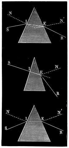
Fig. 21.—Deviation of Light in Passing at Various Incidences through Prisms of Various Angles.
58The refraction of light then depends upon the density of the substance through which it passes, on the angle of incidence of the ray, on the angle of the prism, and also on the colour of the light, about which we shall have something to say presently.
Let us now pass from the prism to the lens; for having once grasped the idea of refraction there will be no difficulty in seeing what a lens really is.
With the prism just considered, placed so that a vertical section is represented by a V, a ray is thrown upwards; if another similar prism be placed with its base in contact with the base of the other, and its apex upwards, so that its section will be represented by a V reversed, Ʌ, it is clear this will turn the rays downwards, so that the rays, on emerging from both prisms will tend to meet each other, as shown, in Fig. 22, where one ray is turned down to the same extent that the other is turned up; so that by the combination of two prisms the two rays are brought to a point, which is called a focus. Now, if instead of putting the prisms base to base, they are put apex to apex, a contrary action takes place, and by this means one is able to 59cause two rays of light to diverge instead of converging, so that the prisms, placed apex to apex, cause the rays to diverge, and when placed base to base they cause the light to converge.
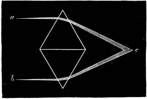
Fig. 22.—Convergence of Light by Two Prisms Base to Base.
If instead of having two prisms merely, there be taken a system having different angles at their apices, and from each prism there be cut a section, beginning by cutting off the apex of the most powerful prism, a slice from below the apex of the next, and a slice below the corresponding part of the next, and so on; and then if these slices be laid on each other so as to form a compound prism, and another similar prism be placed with its base to this one, we get what is represented in Fig. 23. These different slices of prisms become more and more prismatic, that is, they form parts of prisms of greater angle, as they approach the ends. We can imagine a section of such a system as thin as we please. Suppose we had such a section and put it in a lathe, rotating it on the axis A B, we should describe a solid figure, and if we suppose all the angles rounded off, so that it is made thinner and thinner as we recede from the centre, the prism system is turned 60into a lens having the form represented in Fig. 24. In a similar manner, lenses thinner in the middle than at the edges, called concave lenses, can he constructed, some forms of which are represented in section in Fig. 25. It is also obvious that convex lenses of all curves and combinations of curves can be made, some of which appear in Fig. 26.
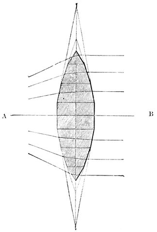
Fig. 23.—Formation of a Lens from Sections of Prisms.
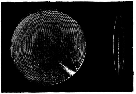
Fig. 24.—Front View and Section of a Double Convex Lens.
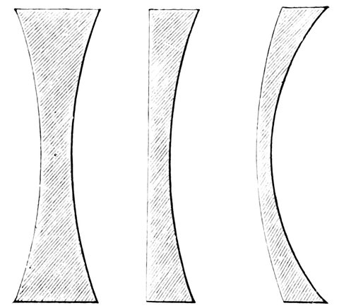
Fig. 25.—Double Concave, Plane Concave, and Concavo-Convex Lenses.
The action of such lenses upon the light proceeding from any source may now be considered. If there is a parallel beam proceeding from a lamp, or from the sun, and it falls on the form of lens, called a convex lens, which bulges out in the middle, we learn from Fig. 27, that the upper part acts like the upper prism just considered and turns the light down, and the lower acts in the reverse manner and turns the light up, and the sides act in a similar manner; and as the inclination of the surfaces of the lens increases as we approach the edge, the rays falling on the parts near the edge are 62turned out of their course more than those falling near the centre, so that we have the rays converged to a point F, called the focus of the lens; and as the rays from an electric lamp are generally rendered parallel by means of the lenses in the lantern, called the condensers, the rays from such a lamp falling on a convex lens will come to a focus at just the same distance from the lens, called its principal focal length as they would do if they came from the sun or stars.
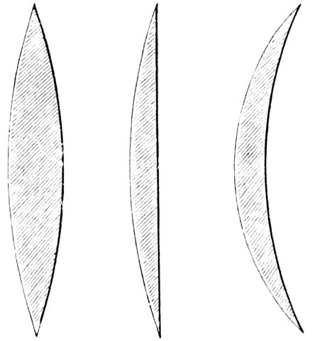
Fig. 26.—Double Convex, Plane Convex, and Concavo-Convex Lenses.
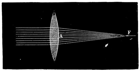
Fig. 27.—Convergence of Rays by Convex Lens to Principal Focus.
So far we have brought rays to a focus, and on holding 63a piece of paper at the focus of the convex lens, as just mentioned, there appears on it a spot of light; and every one knows that if this experiment be performed with the sun, one brings all the rays falling on the lens almost to a point, and the longer waves of light will set fire to the paper; and on this principle burning-glasses are constructed. If, however, the rays are not parallel when falling on the lens, but diverging, they are not brought to a focus so near the lens, and the nearer the luminous source or object is, the further off will the light be brought to a focus on the other side. If matters are reversed, and the luminous source be placed in the focus, the rays of light, when they leave the lens, will converge to the position of the original source; so that there are two points, one on either side of the lens, which are the foci of each other S, S´, Fig. 28, called conjugate foci; as one approaches the lens the other recedes, and vice versâ, and it is obvious that when the one approaches the lens so as to coincide with the principal focus, the other recedes to an infinite distance, and the emergent rays are parallel.
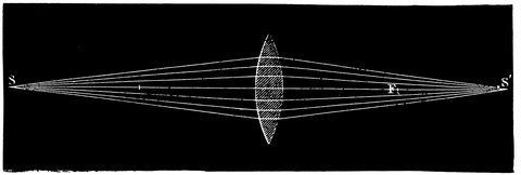
Fig. 28.—Conjugate Foci or Convex Lens.
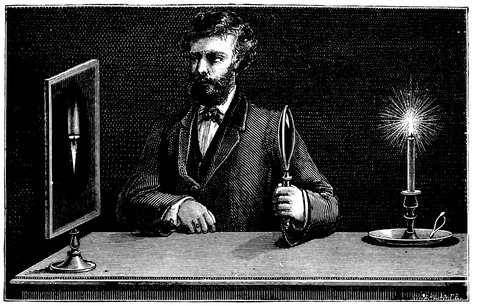
Fig. 29.—Conjugate Images.
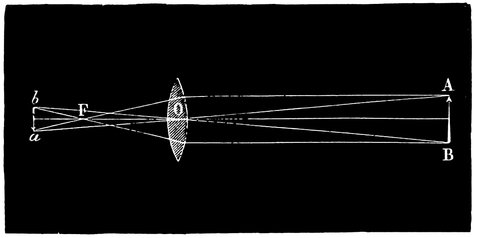
Fig. 30.—Diagram explaining Fig. 29.
Now let us consider how images are formed. If we take a candle, Fig. 29, and hold the lens a little distance away from it, then, on placing a screen of paper just on the other side of the lens, there will be a small flame depicted on it, an exact representation of the real flame: and it is formed in this way: Consider the rays proceeding from the top of the flame, which are 65represented separately in Fig. 30, where A represents the top. One of these rays, A a, passing through the centre of the lens o, will he unaffected because the surfaces through which it passes are parallel to each other; and we know from the property of the lens that all the other rays from A will, on passing through it, be brought to a focus somewhere on A a, depending on the curvature of the lens, and in the case of our lens it is at a.
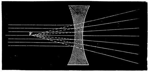
Fig. 31.—Dispersion of Rays by a Double Concave Lens.
In like manner also all the rays from B are brought to a focus at b, and so on with all other parts of A, B, which in this case represents the flame, each will have its corresponding focus; there being cones of rays from every point of the object and to every point of the image, having for their bases the convex lens, and we get an image or exact representation of our candle flame. It will further be noticed that the image a b is smaller than A B, in proportion as the distance a b is less than A B; so that if we increase the focal length of the lens till a b is twice the distance away from the lens, it will become double its present size.
If now the flame be brought nearer the lens, its image a b becomes indistinct; and we must move the screen further away in order to render the image again clear; 66hence the place of the focus depends on the distance of the object, and the candle and its image must correspond to two conjugate foci.
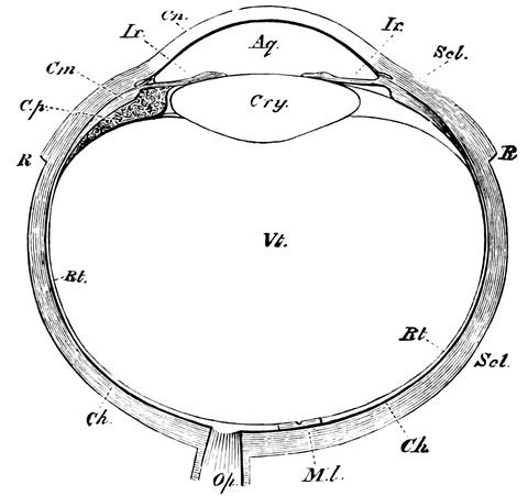
Fig. 32.—Horizontal Section of the Eyeball. Scl, the sclerotic coat; Cn, the cornea; R, the attachments of the tendons of the recti muscles; Ch, the choroid; Cp, the ciliary processes; Cm, the ciliary muscle; Ir, the iris; Aq, the aqueous humour; Cry, the crystalline lens; Vi, the vitreous humour; Rt, the retina; Op, the optic nerve; Ml, the yellow spot.
If now rays be passed from the lantern or sun through a concave lens, Fig. 31, they are not brought to a focus, but are dispersed and travel onwards, as if they came from a point, F, which is called its virtual focus; and if rays are first converged by a convex lens, and then, before they reach the focus are allowed to fall on a concave one, we can, by placing the lenses a certain distance apart, render the converging rays again parallel; or we can make them slightly divergent, as if they came, not from an infinite distance, but from a point a foot or two off. The application of this arrangement will appear hereafter.
67What has now been said on the action of the convex lens will enable us to consider the optical action of the eye, without which we do little in astronomy. As to the way that the brain receives impressions from the eye we need say nothing, for that belongs to the domain of physiology, except indeed this, that an image is formed on the retina by a chemical decomposition, brought about by the dissociating action of certain rays of light in exactly the same way as on a photographic plate. Optically considered, the eye consists of nothing more than a convex lens, Cry, Fig. 32, and a surface, Rt, extending over the back of the eyeball, called the retina, on which the objects are focussed, but the rays of light falling on the cornea Cn, are refracted somewhat, so that it is not quite true to say that the crystalline lens does all the work, but for our present purpose it is sufficiently correct, and we shall consider their combined action as that of a single lens.
The outer coat of the eyeball, shown in section in Fig. 32, is called the sclerotic, with the exception of that more convex part in front of the eye, called the cornea; behind this comes the aqueous humour and then the iris, that membrane of which the colour varies in different people and races. In the centre of this is a circular aperture called the pupil, which contracts or expands according to the brightness of the objects looked at, so that the amount of light passing into the eye is kept as far as possible constant. Close behind the iris comes the crystalline lens, the thickness of which can be altered slightly by the ciliary muscle. In the space between the lens and the back of the eye is a transparent jelly-like substance called the vitreous humour. Finally comes the retina, a most delicate surface chiefly composed 68of nerve fibres. It is on this surface, that the image is formed by the curved surfaces of the anterior membranes, and through the back of the eyeball is inserted the mass of filaments of the optic nerve making communication with the brain; these filaments on reaching the inside of the eye spread out to receive the impressions of light.
Here then, we have a complete photographic camera; the crystalline lens and cornea, separated by the aqueous humour, representing the compound-glass camera lens, and the retina standing in the place of the sensitive plate.
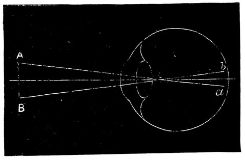
Fig. 33.—Action of Eye in Formation of Images.
The path of the light forming an image on the retina is shown in Fig. 33, where A B is the object, and a b its image, formed in exactly the same way as the image of the candle-flame which we have just considered; in fact, the eye is exactly represented by a photographic camera, the iris acting in the same manner as the stops in the lens, limiting its available area, and by contracting, decreasing the amount of light from bright objects, and at the same time increasing the sharpness of definition, for in the case of the eye, the luminous rays obey the known laws of propagation of light in media of variable form and density, and we have 69only simple refraction to deal with. The next matter to be considered is that the nearer the object A B is to the eye, the larger is the angle A, o, B, and also a, o, b, and therefore the image on the retina is larger; but there is a limit to the nearness to which the object can be brought, for, as we found with the candle, the distance between the lens and the image must be increased as the object approaches, or the curvature of the lens itself must be altered, for if not the ray forming the rays from each point of the object will be too divergent for the lens to be able to bring them to a focus. Now in the eye there is an adjustment of this sort, but it is limited so that objects begin to get indistinct when brought nearer the eye than perhaps six inches, because the rays become too divergent for the lens to bring them to a focus on the retina, and they tend to come to a focus behind the retina, as in Fig. 34; but we may assist the eye lens by using a glass convex lens in front of it, between it and the object. It is for this reason that spectacle glasses are used to enable long-sighted persons to see clearly.
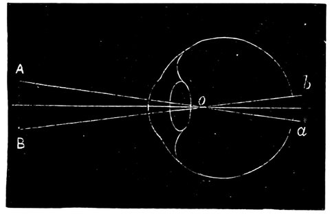
Fig. 34.—Action of a Long-sighted Eye.
We may also use a much stronger lens, and so get the object very near the lens and eye, as in Fig. 35, where 70a b is the object so near the eye that, if it were not for the lens L, its image would not come to a focus on the retina at all. The effect of the lens is to make the rays proceeding in a cone from a and b less divergent, so that after passing through it, they proceed to the eye-lens as if they were coming from the points A and B, a foot or so away from the eye, and so the object a b appears to be a much larger object at a greater distance from the eye.
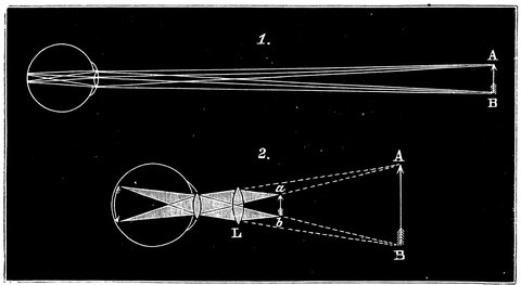
Fig. 35.—1. Diagram showing path of rays when viewing an object at an easy distance. 2. Object brought close to eye when the lens L is required to assist the eye-lens to observe the image when it is magnified.
A convex lens then has the power of magnifying objects when brought near the eye, and its action is clearly seen in Fig. 35, where the upper figure shows the arrow at as short a distance from the eye as it can be seen distinctly with an ordinary eye, and the lower figure shows the same arrow brought close to the eye, and rendered distinctly visible by the lens when a magnified image is thrown on the retina, as if there was a real larger arrow somewhere between the dotted lines at the ordinary 71distance of distinct vision. It is also obvious that the nearer the object can be brought to the eye-lens the more magnified it is, just as an object appears larger the nearer it is brought to the unaided eye.
We have been hitherto dealing with the effect of a convex lens on the rays passing to the eye. We will now deal with a concave one.
We found that the power of adjustment of the normal eye was sufficient to bring parallel rays, or those proceeding from a very distant object, and also slightly diverging rays, to a focus on the retina. Parallel or slightly divergent rays are most easily dealt with, and slightly convergent rays can also be focussed on the retina; but if the eye-lens is too convex, as is the case with short-sighted people, Fig. 36, a concave lens of slight curvature is used to correct the eye-lens and bring the image to a focus on the retina instead of in front of it.
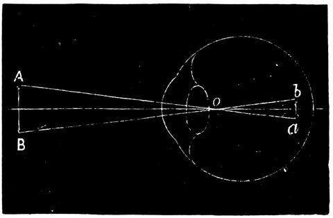
Fig. 36.—Action of Short-sighted Eye.
If the rays are very convergent, as those proceeding from a convex lens and coming to a focus, the lens of a normal eye will bring them to a focus far in front of the retina, as if the person were very short-sighted. But by interposing a sufficiently powerful concave lens the rays are made less convergent or parallel, and the eye-lens 72brings them to a focus on the retina, as if they came from a near object, so the use of convex and concave lenses placed close to the eye is to render divergent or convergent rays nearly parallel, so that the eye-lens can easily focus them, and therefore one of the conditions of the telescope is that the rays which come into our eye shall be parallel or nearly so.
In the telescope as first constructed by Galileo there are two lenses, so arranged that the first, a convex one, A B Fig. 37, converges the rays, while the second, C D, a concave one, diverges them, and renders them parallel, ready for the eye; the rays then, after passing through C D, go to the eye as if they were proceeding along the dotted lines from an object M M, closer to the eye instead of from a distant object, and so, by means of the telescope, the object appears large and close.
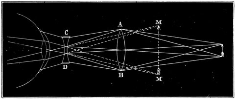
Fig. 37.—Galilean Telescope. A B, convex lens converging rays; C D, concave lens sending them parallel again and fit for reception by the eye.
It is this that constitutes the telescope. But nowadays we have other forms, as we are not content with 74the convex combined with the concave lens, and modern astronomy requires the eyepiece to be of more elaborate construction than those adopted by Galileo and the first users of telescopes, although this form is still used for opera-glasses and in cases where small power only is required. Having the power of converging the light and forming an image by the first convex lens or object glass, as we saw with the candle flame (Fig. 29), and an opportunity of enlarging this image by means of a magnifying or convex eyepiece, we can bring an image of the moon, or any other object, close to the eye, and examine it by means of a convex lens, or a combination of such lenses. So we get the most simple form of refracting telescopes represented in Fig. 38, in which the rays from all points of the object—let us take for instance an arrow—are brought to a focus by the object-glass A, forming there an exact representation of the real arrow. In the figure two cones of rays only are delineated, namely, those forming the point and feather of the arrow, but every other point in the arrow is built up by an infinite number of cones in the same way, each cone having the object-glass for its base. By means of the lens C we are able to examine the image of the arrow B, since the rays from it are thus rendered parallel, or nearly so, and to the eye they appear to come from a much larger arrow at a short distance away. We can draw their apparent direction, and the apparent arrow (as is done in Fig. 37 by the dotted lines), and so the object appears as magnified, or, what comes to the same thing, as if it were nearer.
The difference between this form and that contrived by Galileo is this: in the latter the rays are received by the eyepiece while converging, and rendered parallel 75by a concave lens, while in the former case the rays are received by the eyepiece on the other side of the focus, where they have crossed each other and are diverging, and are rendered parallel by a convex lens.
We may now sum up the use of the eye-lens. The image is brought to a focus on the retina, because the object is some distance off, and the rays from every point, (as from A and B, Fig. 35), on reaching the eye, are nearly parallel; but it is not necessary that they should be absolutely parallel, as the eye is capable of a small adjustment, but if one wishes to see an object much nearer (as in the lower figure), it is impossible to do it unless some optical aid is obtained, for the rays are too divergent, and cannot be brought to a focus on the retina. What does that optical aid effect? It enables us to place the object in the focus of another lens which shall make the rays parallel, and fit for the lens of the eye to focus on the retina, and since the object can by this means be brought close to the lens and eye, it forms a larger image on the retina. Dependent on this is the power of the telescope.

Fig. 38.—Telescope. A, object-glass, giving an image at B; C, lens for magnifying image B.
We shall refer later on to the mechanical construction of the telescope. Here it may be merely stated that 76the smaller ones consist of a brass tube, the object-glass held in a brass ring screwed in at one end of the tube and a smaller tube carrying the eyepiece sliding in and out of the large tube and sometimes moved by a rack and pinion motion, at the other. The larger ones as mounted for special uses will also be fully described farther on.
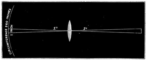
Fig. 39.—Diagram Explaining the Magnifying Power of Object-glass.
The power of the telescope depends on the object-glass as well as on the eyepiece; if we wish to magnify the moon, for instance, we must have a large image of the moon to look at, and a powerful lens to see that image. By studying Fig. 39 the fundamental condition of producing a large image by a lens will be seen. Suppose we wish to look at an object in the heavens, the diameter of which is one degree; if the lens throws an image of that body on to the circumference of a circle of 360 inches, then, as there are 360 degrees in a circle, that image will cover one inch; let the circle be 360 yards, and the image of a body of one degree will cover one yard; and to take an extreme case and suppose the circumference of the circle to be 360 miles, then the image will be one mile in diameter.
77This is one of the principal conditions of the action of the object-glass in enabling us to obtain images which can be magnified by a lens, and by such magnification made to appear nearer to us than they are.
Galileo used telescopes which magnified four or five times, and it was only with great trouble and expense that he produced one which magnified twenty-three times.
Now, after what has been said of focal length, one will not be surprised to hear of those long telescopes produced in the very early days, a few of which are still extant; these show as well as anything the enormous difficulty which the early employers of telescopes had to deal with in the material they employed. One can scarcely tell one end of the telescope from the other; all the work was done in some cases by an object-glass not more than half an inch in effective diameter.
It might be supposed that those who studied the changes of places and the positions of the heavenly bodies would have been the first to gain by the invention of the telescope, and that telescopes would have been added to the instruments already described, replacing the pointers. For such a use as this a telescope of half an inch aperture would have been a great assistance. But things did not happen so, because the invention of the telescope gave such an impetus to physical astronomy that the whole heavens appeared novel to mankind. Groups of stars appeared which had never been seen before; Jupiter and Saturn were found to be attended by satellites; the sun, the immaculate sun, was determined after all to have spots, and the moon was at once set upon and observed with diligence and care; so that there was a very good reason why people should not limit the powers of the telescope to employing it to determine 78positions only. The number of telescopes was small, and they could not be better employed than in taking a survey of all the marvellous things which they revealed. It was at this time that the modern equatorial was foreshadowed. Galileo, and his contemporaries Scheiner and others, were observing sun-spots, and the telescope, Fig. 40, which Scheiner arranged, a very rough instrument, with its axis parallel to the earth’s axis, and allowed to turn so that Scheiner might follow the sun for many hours a day, was one of the first. This instrument is here reproduced, because it was one of the most important telescopes of the time, and gathered in to the harvest many of the earliest obtained facts.
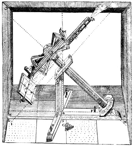
Fig. 40.—Scheiner’s Telescope.
Since by means of little instruments like these, so much of beauty and of marvel could be discovered in the skies, it is no wonder that every one who had 79anything to do with telescopes strained his nerves to make them of greater power, by which more marvels could be revealed.
It was not long before those little instruments of Scheiner expanded into the long telescopes to which reference has been made. But there was a difficulty introduced by the length of the instrument. The length of the focus necessary for magnification spread the light over a large area, and therefore it was necessary to get an equivalent of light by increasing the aperture of the object-glasses in order that the object might be sufficiently bright to bear considerable magnification by the eyepiece,—and now arose a tremendous difficulty.
One part of refraction, namely, deviation, enables us to obtain, but the other half, dispersion, prevents our obtaining, except under certain conditions, an image we can make use of. By dispersion is meant the property of splitting up ordinary light into its component colours, of which we shall say more in dealing with spectrum analysis. If we wish to get more light by increasing the aperture of the telescope, the deviation of the light passing through the edge of the object-glass is increased, and with it the dispersion, the result of this increase of deviation. If the light of the sun be allowed to fall through a hole into a darkened chamber, and then through a prism, Fig. 41, it is refracted, and instead of having an exact reproduction of the bright circle we have a coloured band or spectrum. The white light when refracted is not only driven out of its original course—deviated—but it is also broken up—dispersed—into many colours. We have a considerable amount of colour; and this the early observers found when they increased the size of their telescopes, 80for it must be remembered that a lens is only a very complex prism.
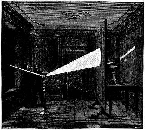
Fig. 41.—Dispersion of Light by Prism.
First, they increased the size by enlarging the object-glasses, and not the focal length; but when they had done that they had that extremely objectionable colour which prevented them seeing anything well. The colour and indistinctness came from an overlapping of a number of images, as each colour had its own focus, owing to varying refrangibilities. They found, therefore, that the only effective way of increasing the power of the telescope was by increasing its focal length so as to reduce the dispersing action as much as possible, and so enlarging the size of the 81actual image to be viewed, without at the same time increasing the angular deviation of the rays transmitted through the edges of the lens. The size of the image corresponding to a given angular diameter of the object is in the direct proportion of the focal length, while the flexure of the rays which converge to form any point of it is in the same proportion inversely.
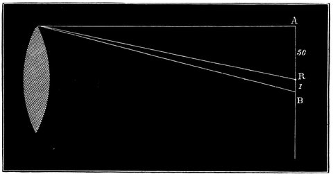
Fig. 42.—Diagram Showing the Amount of Colour Produced by a Lens.
To take an example. In the case of an object-glass of crown-glass, the space over which the rays are dispersed is one-fiftieth of the distance through which they are deviated, and it will be seen by reference to Fig. 42, that if the red rays are at R, and the blue at B, the distance A B is fifty times R B, and as these distances depend on the diameter of the lens only, we can increase the focal length, and so increase the size of the image without altering the dispersion R B, and so throw the work of magnifying on the object-glass instead of on the eyepiece, which would magnify R B equally with the image itself. So that in that time, and in the time of Huyghens, telescopes of 100, 200, and 300 feet focal 82length were not only suggested but made, and one enthusiastic stargazer finished an object-glass, the focal length of which was 600 feet. Telescopes of 100 and 150 feet focal length were more commonly used. The eyepiece was at the end of a string, and the object-glass was placed free to move on a tall pole, so that an observer on the ground, by pulling the string, might get the two glasses in a line with the object which he wished to observe.
So it went on till the time of Sir Isaac Newton, who considered the problem very carefully—but not in an absolutely complete way. He came to the conclusion, as he states in his Optics, that the improvement of the refracting telescope was “desperate;” and he gave his attention to reflecting telescopes, which are next to be noticed.
Let us examine the basis of Sir Isaac Newton’s statement, that the improvement of the refracting telescope was desperate. He came to the conclusion that in refraction through different substances there is always an unchanged relation between the amount of dispersion and the amount of deviation, so that if we attempt to correct the action of one prism by another acting in an opposite direction in order to get white light, we shall destroy all deviation. But Sir Isaac Newton happened to be wrong, since there are substances which, for equivalent deviations, disperse the light more or less. So by means of a lens of a certain substance of low dispersive power we can form an image slightly coloured, and we can add another lens of a substance having a high dispersive power and less curvature and just reverse the dispersion of the first lens without reversing all its deviating power.
83The following experiments will show clearly the application of this principle. We first take two similar prisms arranged as in Fig. 43. The last through which the light passes corrects the deviation and dispersion of the first. We then take two prisms, one of crown glass and the other of flint glass, and since the dispersion of the flint is greater than that of the crown, we imagine with justice that the flint-glass prism may be of a less angle than the other and still have the same dispersive power, and at the same time, seeing that the angles of the prisms are different, we may expect to find that we shall get a larger amount of deviation from the crown-glass prism than from the other.
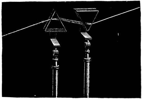
Fig. 43.—Decomposition and Recomposition of Light by Two Prisms.
If then a ray of light be passed through the crown-glass prism, we get the dispersion and deviation due to the prism A Fig. 44, giving a spectrum at D. And now we take away the crown glass and place in its stead a prism of flint glass inverted; the ray in this instance is deviated less, but there is an equal amount of colouring at D´. If now we use both prisms, acting in opposite 84directions, we shall be able to get rid of the colours, but not entirely compensate the deviation. We now place the original crown-glass prism in front of the lantern and then interpose the flint-glass prism, so that the light shall pass through both. The addition of this prism of flint, of greater dispersive power, combines, or as it were shuts off, the colour, leaving the deviation uncompensated, so that we get an uncoloured image of the hole in front of the lantern at D˝. This is the foundation of the modern achromatic telescope.
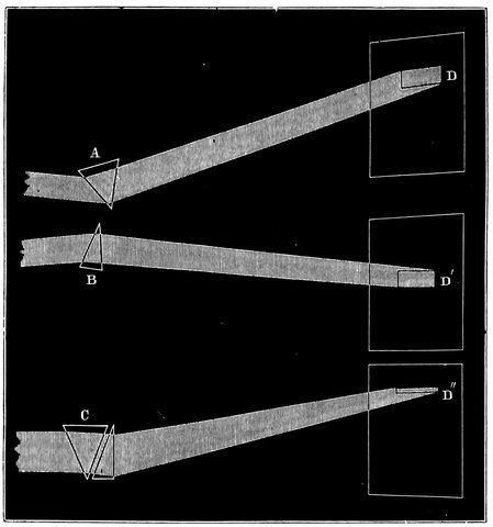
Fig. 44.—Diagram Explaining the Formation of an Achromatic Lens. A, crown-glass prism; B, flint-glass prism of less angle, but giving the same amount of colour; C, the two prisms combined, giving a colourless yet deviated band of light at D˝.
85Another method of showing the same thing is to bring a V-shaped water-trough into the path of the rays from the lantern; then, while no water is in it, the beam of light passing through it is absolutely uncoloured and undeviated. In this case we have no water inclosed by these surfaces, and it is not acting as a prism at all. If, however, a prism of flint glass, a substance of high dispersive power, is introduced into it, with its refracting edge upwards, it destroys the condition we had before, and we have a coloured band on the screen, because the glass that the prism is made of has the faculty of strong dispersion in addition to its deviation. We can get rid of that dispersion by throwing dispersion in a contrary direction by filling up the trough with water, and so making, as it were, a water prism on either side of the glass one, water being a substance of low dispersive power. We have a colourless beam thrown on the screen, which is deviated from the original level, because the water prisms are together of a greater angle than the glass one.
The experiments of Hall and Dolland have resulted in our being able to combine lenses in the same way that we have here combined prisms, bearing in mind what has been said in reference to the action of lenses being like that of so many prisms; and we may consider two lenses, one of crown and the other of flint glass, Fig 45. The crown glass being of a certain curvature will give a certain dispersion; the flint glass, in consequence of its great dispersive power, will require less curvature to correct the crown glass. What will happen will be this: assuming the second lens to be away, the rays will 86emerge from the first (convex) lens and form a coloured image at A. But if the second flint-glass concave lens be interposed it will, by means of its action in a contrary direction, undo all the dispersion due to this first lens and a certain amount of deviation, so that we shall get the combination giving an almost colourless image at B.
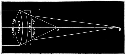
Fig. 45.—Combination of Flint- and Crown-glass Lenses in an Achromatic Lens.
It will not be absolutely colourless, for the reasons which will be now explained. If light be passed through different substances placed in hollow prisms, or through prisms of flint and crown glass, and the spectra thus produced be observed, we find there are important differences. When we expand the spectra considerably, we see that the action of these different substances is not absolutely uniform, some colours extending over the spectrum further than others. In the case of one kind of glass the red end of the spectrum is crushed up, while in the other we have the red end expanded.
This is called the irrationality of the spectrum produced by prisms of different substances. The crown and the flint-glass lenses—and for telescopes we must use such glass—give irrational spectra, so that the achromatic telescope is not absolutely achromatic, in consequence 87of this peculiarity; for if R, G, B, Fig. 46, are the centres of the red, green, and violet in the spectrum given by a prism composed of the glass of which one lens is made, and R´, G´, B´, are those of the other, if the lenses are placed so as to counteract each other, and are of such curves that the reds and violets are combined, the greens will remain slightly outstanding. Suppose, as in the drawing, the second prism disperses the violet as much as the first one does, then, when these are reversed they will exactly compensate red and violet. But the second one acts more strongly on the green than the first, which will be over-compensated; and if we weaken the second prism so that the green and red are correct, then the violet will be slightly outstanding, which in practice is not much noticed, except with a very bright object when there is always outstanding colour.

Fig. 46.—Diagram Illustrating the Irrationality of the Spectrum.
This is, however, not a matter of any very great importance for ordinary work, since the visual rays all lie in the neighbourhood of the yellow, so that opticians take care to correct their lenses for the rays in this part of the spectrum, and at the same time, as a matter of necessity, over-correct for the violet rays, that is, reverse the dispersion of the exterior lens, so that the violet rays have a longer instead of a shorter focus than the 88red, and, therefore, in looking at a bright object, such as a first magnitude star, it appears surrounded by a violet halo; with fainter objects the blue light is not of sufficient intensity to be visible. It is, therefore, always preferable to correct for the most visible rays and leave the outstanding violet to take care of itself; but nevertheless various proposals have been made to get rid of it. Object-glasses containing fluids of different kinds have been tried, but they have never become of any practical value, and it does not seem probable that they ever will.
In order to get rid of the outstanding violet colour when the remainder of the spectrum was corrected, Dr. Blair constructed object-glasses the space between the lenses of which were filled with certain liquids, generally a solution of a salt of mercury or antimony, with the addition of hydrochloric acid; for in the spectrum given by the metallic solution the green is proportionally nearer the red than is the case with the spectrum produced by hydrochloric acid, so that by the adjustment of the different solutions he exactly destroyed the outstanding colour of the ordinary combination. In this way Sir John Herschel tells us he was able to construct lenses of three inches aperture and only nine inches focal length, free from chromatic and spherical aberration.
It was proposed by Mr. Barlow to correct a convex crown-glass lens for chromatic aberration by a hollow concave lens containing bisulphide of carbon, a highly dispersive fluid, having double the power of flint glass. This lens was placed in the cone of rays between the object-glass and the eyepiece. Its surfaces were concavo-convex, calculated to destroy spherical aberration, and its distance from the object-glass was varied until 89exact achromatism was obtained. A telescope of this principle of eight inches aperture was made by Mr. Barlow, which proved highly satisfactory. In the early part of the last century it was proposed by Wolfius to interpose between the object-glass and eyepiece a concave lens in order to give greater magnification of the image, with a slight increase of focal length; if an ordinary lens be used the achromatism of the images given by the object-glass will be destroyed. Messrs. Dolland and Barlow, however, proposed to make the concave lens achromatic, so that the image is as much without colour when the lens is used as without it. Mr. Dawes found such a lens to work extremely well. These lenses, usually called “Barlow lenses,” are generally made about one inch in diameter, and by varying their distance from the eyepiece the image is altered in size at pleasure.
In the reflecting telescope, with which we will now proceed to deal, there is an absence of colour; but the reflector is not without its drawbacks, for there are imperfections in it as great as those we have been considering in the case of the refractor.
We have now dealt with the refraction of light in general, including deviation and dispersion, in order to see how it can assist us in the formation of the telescope; and we have shown how the chromatic effect of a single lens can be got rid of by employing a compound system composed of different materials, and so we have got a general idea of the refracting telescope. We have now to deal with another property of light, called reflection; and our object is to see how reflection can help us in telescopes.
In the case of reflection we get the original direction of the ray changed as in the case of refraction, but the deviation is due to a different cause. Take a bright light, a candle will do, and a mirror fixed so that the light falls on its surface and is thrown back to the eye, Fig. 47, we see the image of the candle apparently behind the mirror; the rays of light falling on the mirror are reflected from it at exactly the same angle at which they reach it. This brings us in the presence of the first and most important law of reflection; and it is this, at whatever angle the light falls on a mirror, at that angle will it be reflected. As it is usually expressed, the angle 91of incidence, which is the angle made by the incident ray with an imaginary line drawn at right angles to the mirror, called the normal, is equal to the angle of reflection, that is, the angle contained by the reflected ray, and the normal to the surface. In order, therefore, to find in what direction a ray of light will travel after striking a flat polished surface, we must draw a line at right angles to the surface at the point where the ray impinges on it, then the reflected ray will make an angle with the normal equal to that which the incident ray makes, or the angles of incidence and reflection will be equal.
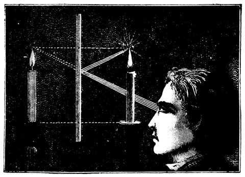
Fig. 47.—Diagram Illustrating the Action of a Reflecting Surface.
Very simple experiments, which every one can make will show us the laws which govern the phenomena of reflection. Let us employ a bath of mercury for a reflecting surface, and for a luminous object a star, the rays of which, coming from a distance which is practically infinite, to the surface of the earth, may be considered exactly parallel. The direction of the beams of light coming from the star, and falling on the 92mirror formed by the mercury, is easily determined by means of a theodolite, Fig. 48. If we look directly at the star, the line I´ S´ of the telescope indicates the direction of the incident luminous rays, and the angle S´ I´ N´, equal to the angle S, I, N, is the angle of incidence, that is to say, that formed by the luminous ray with the normal to the surface at the point of incidence.
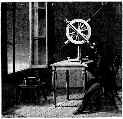
Fig. 48.—Experimental Proof that the Angle of Incidence = Angle of Reflection.
In order to find the direction of the reflected luminous rays, we must turn the telescope on its axis, until 93the rays reflected by the surface of the mercury bath enter it and produce an image of the star. When the image is brought to the centre of the telescope, it is found that the angle R´ I´ N´ is equal to the angle of reflection N, I, R. Thus, in reading the measure on the graduated circle of the theodolite the angle of reflection can be compared with the angle of incidence.
Now, whatever may be the star observed, and whatever its height above the horizon, it is always found that there is perfect equality between these angles. Moreover, the position of the circle of the theodolite which enables the star and its image to be seen evidently proves that the ray which arrives directly from the luminous point and that which is reflected at the surface of the mercury are both in the same vertical plane.
Now this demonstrates one of the most important laws of reflection. The laws of refraction do not deal directly with the angles themselves, but with the sines of the angles; in reflection the angles are equal; in refraction the sines have a constant relation to each other.
So far we have dealt with plane surfaces, but in the case of telescopes we do not use plane surfaces, but curved ones, so we will proceed at once to discuss these.
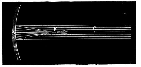
Fig. 49.—Convergence of Light by Concave Mirror.
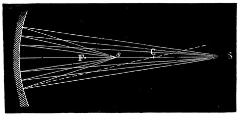
Fig. 50.—Conjugate Foci of Convex Mirror.
In Fig. 49, A represents a curved surface, such as that of a concave mirror, the centre of curvature being C. Now we can consider that this curved surface is made up of an infinite number of small plane surfaces, and since all lines drawn from the centre, C, to the mirror, will be at right angles to the surface at the points where they meet it, we find, from our experiment with the plane mirror, that rays falling on the mirror at these points will be reflected so that the angles on either side of each of these lines shall be equal; so, for instance, in Fig. 49, we wish to find to what point the upper ray will be reflected, and we draw a line from the centre, C, to the point where it falls on the mirror, and then draw another line from that point making the angle of reflection equal to that made by the incident ray, and we can consider the small surface concerned in reflection flat, so that the ray will in this case be reflected to F. If now we take any other ray, and perform the same operation we shall find that it is also reflected nearly to F, and so on with all other parallel rays falling on the mirror; and this point, F, is therefore said to be the focus of the mirror. 95If now the rays, instead of falling parallel on the mirror, as if they came from the sun or a very distant object, are divergent, as if they came from a point S, Fig. 50, near the mirror, the rays approach nearer to the lines drawn from the centre to the mirror, one of which is represented by the dotted line; or, in other words, the angles of incidence become reduced, and so the angles of reflection will also be reduced, and the focus of the rays from S will approach the centre of the mirror, and be at s; just so it will be seen that if an illuminated point be at s, its focus will be at S, and these two points are therefore called conjugate foci.
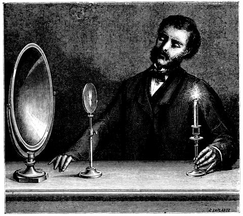
Fig. 51.—Formation of Image of Candle by Reflection.
If a candle is held at a short distance in front of a concave mirror, as represented in Fig. 51, its image appears on the paper between the candle and the mirror, so that the rays from every point of the flame are brought to a focus, and produce an image just as the image is produced by a convex lens. If we study Fig. 52 the formation of this image will be clearly understood. First we must note that the rays A, C, a, and B, C, b, which pass through the centre of curvature of the mirror C, will fall perpendicularly on the surface, and be reflected back on themselves, so that the focus of the part a of the arrow will be somewhere on A a, and that of B on B b, and by drawing another ray we shall find it reflected to a, which will be the focus of the point A, and so also by drawing another line from B, we shall find it is reflected to b, which is the focus of the part B; and we might repeat this process for every part of the arrow, and for every ray from those parts. We now see that since the 97rays A a and B b cross each other at C, the distance from a to b bears the same proportion to the distance from A to B as their respective distances from the point C; or, in other words, the image is smaller than the object in the same proportion as the distance from the image to C is smaller than the distance from the object to C. Now, in dealing with the stars, which are at a practically infinite distance, the rays are parallel, and will be brought to a focus half-way between the mirror and its centre of curvature. In this case, therefore, the distance from the image to the mirror is equal to that from the image to the centre, so that we can express the size of the image by saying that it is smaller than the object, in proportion as its distance from the mirror is smaller than the distance of the object from C; and as it makes little difference whether we measure the distance of the stars from C or from the mirror, and as C is not always known, we can take the relation of the distances of the object and image from the mirror as representing the proportionate sizes of the two.
We will now consider the case of rays falling on a mirror curved the other way, that is, a convex mirror. Let us consider the ray impinging at D, Fig. 53, which would go on to C, the centre of the mirror. Now, as C D is drawn from the centre, it is at right angles to the mirror at D, and the ray L D, being in the same straight line on the opposite side, will also be at right angles, and will be reflected back on itself. Now take the ray I A, draw C E through A, then E A will be perpendicular to the surface at A, and I A E will be the angle of incidence, and E A G the angle of reflection, so that this ray A G will be reflected away from L D, and so will all the other rays falling on the mirror as K B: and if we continue 98the lines G A and H B backwards, they will meet at M, and therefore the rays diverge from the mirror as if they came from a point at M, and this point is called the virtual focus.
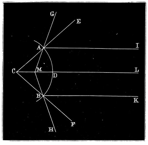
Fig. 53.—Reflection of Rays by Convex Mirror.
So much for parallel rays. Next let us consider another case which happens in the telescope, namely, where converging rays fall on a convex mirror, as in Fig. 53, where we consider the light proceeding to the mirror from a converging lens along the lines H B and G A, these will be made parallel, at B K and A F, after reflection, and it is manifest that by making the mirror sufficiently convex, these rays, tending to come to a focus at M, could be rendered divergent; and if the curvature is decreased by making the centre of curvature at a certain distance beyond C, it will be seen at once by the diagram that these rays will after reflection, converge towards L and will come to a focus in front of the mirror at a point further in front than C is behind it, so that they have 99been rendered less convergent only by the mirror in this supposed case.
It will be seen from what has been stated here and in Chapter V., that we get nearly the same results from reflection as we did from refraction when we were considering the functions of glasses instead of mirrors; that a concave mirror acts exactly as a convex lens, and vice versâ, so that they can be substituted the one for the other. If we take a mirror, and allow the light to fall on it from a lamp, no one will have any difficulty in seeing that the mirror grasps the beam, and forms an image which is seen distinctly in front of the mirror, just as one gets an image from a convex lens behind it.
The point we have next to determine is how we can utilise the properties of reflection for the purposes of astronomical observation. Many admirable plans have been suggested. The first that was put on paper was made by Gregory, who pointed out that if we had a concave mirror, we should get from this mirror an image of the object viewed at the focus in front of it, as in Fig. 51. Of course we cannot at once utilise this focal image by using an eyepiece in the same way as we do in a refractor, because the observer’s head would stop the light, and the mirror would be useless, and all the suggestions which have been made, have reference to obtaining the image in such a position that we are able to view it conveniently.
Gregory, the Scottish astronomer above referred to, in 1663 suggested a method, and it has turned out to be a good one, of utilizing reflection by placing a small mirror D C, Fig. 54, on the other side of the focus A of the large one, at such a distance that the image at A is again focussed at B by reflection from the small mirror; and at B we get of course an enlarged image of A. The rays of light proceeding to B would, 101however, be intercepted by the large mirror, unless an aperture were made in the large mirror of the size of the small one through which the rays could pass and be rendered parallel by means of an eyepiece placed just behind the large mirror. So that towards the object is the small mirror C, and there is an eyepiece E, which enables the image of the object to be viewed after two reflections, first from the large mirror and then from the small one. Mr. Short (who made the best telescopes of this construction, and did much for the optical science of the last century) altered the position of the small mirror with reference to the focus of the large one, by sliding it along the tube by a screw arrangement, F, and so was enabled to focus both near and distant objects without altering the eyepiece.
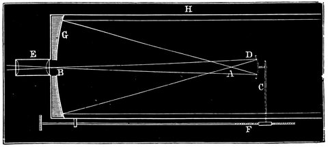
Fig. 54.—Reflecting Telescope (Gregorian).
But before this was put into practice, Sir Isaac Newton (in 1666) made telescopes on a totally different plan.
The eyepiece of the Newtonian telescope is at the side of the tube, and not at the end, as in Gregory’s. We have next to inquire how this arrangement is carried out, and, like most things, it is perfectly simple when one 102knows how it is done. There is a large mirror at the bottom of the tube as in the Gregorian, but not perforated, and the focus of the mirror would be somewhere just in front of the end of the tube. Now in this case we do not allow the beam to get to the focus at all in the tube or in front of it; but before it comes to the focus it is received on a small diagonal plane surface m, and thus it is at once thrown outwards at right angles through the side of the tube, and comes to a focus in front of an eyepiece, placed at the side, ready to be viewed the same as an image from a refractor (Fig. 55).
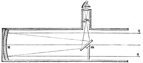
Fig. 55.—Newton’s Telescope.
The next arrangement is one which Mr. Grubb has recently rescued from obscurity, and it is called the Cassegrainian form. It will be seen on referring to that, Fig. 56, if the small mirror, C, were removed, the rays from the mirror A B would come to a focus at F.
In the Gregorian construction a concave reflector was used outside that focus (at C, Fig. 54), but Cassegrain suggested that if, instead of using a concave reflector outside the focus, a reflector with a convex surface were placed inside it, we should arrive at very nearly the same result, provided we retain the hole in the large mirror. The converging rays from A B will fall on the 103convex surface of the mirror C, which is of such a curvature and at such a distance from F, the focus of the large mirror, that the rays are rendered less converging, and do not come to a focus until they reach D, where an image is formed ready to be viewed by the eyepiece E. It appears from this, that the convex mirror is in this case acting somewhat in the same manner as the concave lens does in the Galilean telescope.
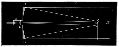
Fig. 56.—Reflecting Telescope (Cassegrain).
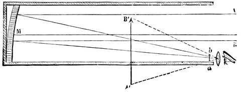
Fig. 57.—Front View Telescope (Herschel).
Then, lastly, we have the suggestion which Sir William Herschel soon turned into more than a suggestion. The mirror M in this arrangement is placed at the bottom of the tube as in the other forms, but, instead of being placed flat on the bottom it is slightly tipped, so that 104if the eyepiece is placed at the edge of the extremity of the tube all parallel rays falling on the mirror are reflected to the side of the tube at the top where the eyepiece is, instead of being reflected to a convex or other mirror in the middle.
This is called the front view telescope, and it enabled Sir William Herschel to make his discoveries with the forty-feet reflector. With small telescopes this form could not be adopted, as the observer’s head would cover some part of the tube and obstruct the light, but with large telescopes the amount of light stopped by the head is small in proportion to what would be lost by using a small mirror.
These are in the main the four methods of arranging reflecting telescopes—the Gregorian, the Cassegrainian, the Newtonian, and the Herschelian.
In order to make large reflectors perfect—large telescopes of short focus, because that is one of the requirements of the modern astronomer—we have to battle against spherical aberration.
We have already seen that the power of substances to refract light differs for different colours, and we have seen the varied refraction of different parts of the spectrum, and the necessity of making lenses achromatic. Now there is one enormous advantage in favour of the reflector. We do not take our light to bits and put it together again as with an achromatic lens. But curiously enough, there is a something else which quite lowers the position of the reflector with regard to the refractor. Although, in the main all the light falling in parallel lines on a concave surface is reflected to a focus, this is only true in a general sense, because, if we consider it, we find an error which increases very rapidly 105as the diameter of the mirror increases or as the focal length diminishes. For instance, D I, Fig. 58, is the segment of a circle, or the section of a sphere—if we deal with a solid figure. D C, E G and H I, are three lines representing parallel rays falling on different parts of it. According to that law which we have considered, we can find where the ray E G will fall. We draw a line L, G, from the centre to the point of reflection, and make the angle F G L, equal to the angle of incidence E G L; then F will be the focus, so far as this part of the mirror is concerned. Now let us repeat the process for the ray H I, and we shall find that it will be reflected to K, a point nearer the mirror than F, and it will be seen that the further the rays are from the axis D C, the further from the point F is the light reflected; so that if we consider rays falling from all parts of the reflecting surface, a not very large but a distinctly visible surface is covered with light, so that a spherical surface will not bring all the rays exactly to a point, and with a spherical mirror we shall get a blurred image. We can compare this imperfection of the reflector, called spherical aberration, with the chromatic aberration of the object-glass.
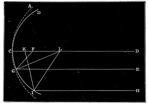
Fig. 58.—Diagram Illustrating Spherical Aberration.
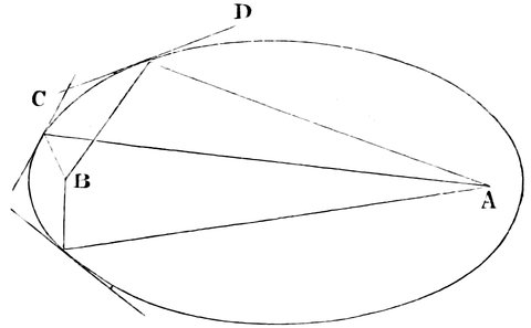
Fig. 59.—Diagram Showing the Proper Form of Reflector to be an Ellipse.
Newton early calculated the ratio of imperfection depending upon these properties of light, first of dispersion and then of spherical aberration, and he found that in the refracting telescope the chromatic aberration was more difficult to correct and get rid of than the spherical aberration of the reflector, so that in Newton’s time, before achromatic lenses were constructed, the reflector with its aberration had the advantage. It must now be explained how this difficulty is got over. What is required to produce a mirror capable of being used for astronomical purposes, is to throw back the edges of the mirror to the dotted line A C I, Fig. 58, which will make the margin of the mirror a part of a less concave mirror, and so its focus will be thrown further from itself—to F, instead of to K. Now let us consider what curve this is, that will throw all the rays to one point. It is an ellipse, as will be seen by reference to Fig. 59, in which, instead of having a spherical surface the 107section of which is a circle, we deal with a surface whose section is an ellipse.
It will be seen in a moment, that by the construction of an ellipse any light coming in any direction from the point A, which represents one of the foci of the curve, must necessarily be reflected back to the other focus, B, of the curve, for it is a well-known property of this curve that the angles made with a tangent C D, by lines from the foci are equal; and the same holds good for the angles made at all other tangents; and it will be seen at once that this is better than a circular curve, because by making the distance between the foci almost infinite we shall have the star or object viewed at one focus and its image at the other; if we use any portion of the reflecting surface we shall still get the rays reflected to one point only. It must also be noticed, that unless we have an ellipse so large that one focus shall represent the sun or a particular star we want to look at, this curve will not help us in bringing the light to one point, but if we use the curve called the parabola, which is practically an ellipse with one focus at an infinite distance, we do get the means of bringing all the rays from a distant object to a point. Hence the reflector, especially when of large diameter, is of no use for astronomical purposes without the parabolic curve.
That it is extremely difficult to give this figure may
be gathered from Sir John Herschel’s statement, that
in the case of a reflecting telescope, the mirror of
which is forty-eight inches in diameter and the focal
distance of which is forty feet, the distance between
the parabolic and the spherical surface, at the edges
of the mirror, will be represented by something less
than a twenty-one thousandth part of an inch, or, more
108accurately, 1
21333 inch. In Fig. 58 the point A represents
the extreme edge of the curve of the parabolic mirror,
and D that of the circular surface before altered into a
parabola.
At the time of Sir William Herschel the practical difficulties in constructing large achromatic lenses led to the adoption by him of reflectors beginning with small apertures of six inches to a foot, and increasing till he obtained one of four feet in diameter and forty-six feet focal length. This has been surpassed by Lord Rosse, whose well-known telescope is six feet diameter, and fifty-three feet focal length. Mr. Lassell, Mr. De La Rue, M. Foucault and Mr. Grubb, have also more recently succeeded in bringing reflectors to great perfection.
How the work has been done will be fully stated in the sequel.
We have considered the telescope as a combination of an object-glass and eyepiece in the one case, and of a speculum and eyepiece in the other; that is to say, we have discussed the optical principles which are applied in the construction of refracting and reflecting telescopes, the telescope being taken as consisting of an object-glass or speculum and an eyepiece of the most simple form, viz., a simple double convex lens.
We must now go into detail somewhat on the subject of eyepieces, and explain the different kinds.
It will be recollected that when we spoke of the object-glass, its aberration, both chromatic and spherical, was mentioned. Now every ordinary lens has these errors, and eyepieces must be corrected for them, but this is not done in exactly the same way as with object-glasses.
In the case of eyepieces the error is corrected by using two lenses of such focal lengths or at such a distance apart that each counteracts the defects of the other; not by using two kinds of glass as in the case of the object-glass, but by so arranging the lenses that the coloured rays produced by the first lens shall fall at 110different angles of incidence on the second and become recombined.
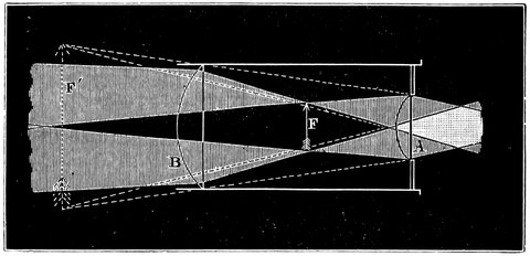
Fig. 60.—Huyghens’ Eyepiece.
Let us take the case of a well-known eyepiece, called the Huyghenian eyepiece, after its inventor. It consists of two plano-convex lenses, A and B Fig. 60, with their convexities turned towards the object-glass, and having their focal lengths in the proportion of three to one. The strongest lens, A, being next the eye, the lens B is placed inside the focus of the object-glass, so that it assists in bringing the image, say of a double star, to a focus at F, half way between the lenses, and nearer to the object-glass than it would have been without the lens. This image is then viewed by the eye-lens, A, and a magnified image of it seen apparently at F´, as has been before explained. Now let us see how the fieldlens renders this combination achromatic. Let us consider the path of a ray falling on the lens near B, shown in section in Fig. 61: it is there refracted, but, the blue rays being refracted more than the red, there will be two rays produced, r and v, giving of course a coloured edge to the image; but when this image is 111viewed by the eye-glass, A, it no longer appears coloured, for the ray v, falling nearer the axis of A, is less bent than r, and they are rendered nearly parallel and appear to proceed from the point F´ where the whole image appears without colour. In order to get the best result with this form of eyepiece the focal length of the fieldlens should be three times that of the eye-lens and they should be placed at a distance of half their joint focal lengths apart.
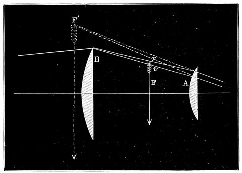
Fig. 61.—Diagram Explaining the Achromaticity of the Huyghenian Eyepiece.
The next eyepiece which comes under consideration is that called Ramsden’s, Fig. 62. It consists of two plano-convex lenses of the same focus, A and B, placed at a distance of two-thirds of the focal length of either apart; they are both on the eye side of the focus of the telescope, and act together, to render the rays parallel and give a magnified virtual image of F´F.
This eyepiece is not strictly achromatic, but it suffers 112least of all lenses from spherical aberration; it also has the advantage of being placed behind the focus of the object-glass, which makes it superior to others in instruments of precision, as we shall presently see.
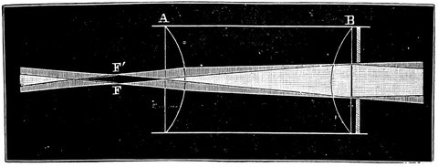
Fig. 62.—Ramsden’s Eyepiece.
It must be remembered that these eyepieces give an inverted image—or rather the object glass gives an inverted image, and the eyepiece does not right it again; but there are eyepieces that will erect the image, and Rheita’s is one of this kind. It is, as will be seen from Fig. 63, merely a second application of the same means that first inverts the object, namely, a second small telescope. A is the object-glass, a b the image inverted in the usual way; B is an ordinary convex lens sending the rays from a and b parallel. Now, instead of placing the eye at C, as in the ordinary manner, another small lens, acting as an object-glass, is placed in the path of the rays, bringing them to a focus at a´, b´, and forming there an erect image which is viewed by the eye-lens D. This is the erecting eyepiece or “day eyepiece,” of the common “terrestrial telescope.” Dollond substituted an Huyghenian eyepiece for the eye-lens D, and so made what is called his four-glass eyepiece.
113Dr. Kitchener devised and Mr. G. Dollond made an alteration in this eyepiece in order to vary its power at pleasure. It is done in this way: The size of the image a´ b´ depends upon the relation of the distances a B and E a´, which can be varied by altering the distance of the combination of the lenses B and E, from the image a b, and so making a´ b´ larger and at a focus further from E; the tube carrying d slides in and out, so that it can be focussed on a´ b´ at whatever distance from E it may be. This arrangement is called Dollond’s Pancratic eyepiece.

Fig. 63.—Erecting or day eyepiece.
On the sliding tube carrying the lens D, or rather the Huyghenian eyepiece in place of the single lens, are marked divisions, showing the power of the eyepiece when drawn out to certain lengths, so that if we want the eyepiece to magnify say 100 times, the tube carrying the eye-lens is drawn out to the point marked 100, and the whole eyepiece moved in or out of the telescope tube by the focussing screw, until the image of the object viewed is focussed in the field of the eyepiece D. To increase the power, we have only to draw out the eyepiece D, and move the whole combination nearer to the object-glass so as to throw the image a´ b´ further from the lens E. This eyepiece, though so convenient for changing powers, is little used, owing perhaps chiefly to 114four lenses being required instead of two, hence a loss of light, so a stock of eyepieces of various powers is generally found in observatories. When very high powers are required, a single plano-convex lens is sometimes used, but although there is less loss of light in this case, the field of view is so contracted in comparison with that given with other eyepieces that the single lens is seldom used. This form is, however, adopted in Dawes’ solar eyepiece, to be hereafter mentioned, and a number of lenses are in this case fixed in holes near the circumference of a disc of metal which turns on its centre, so that by rotating the disc the lenses come in succession in front of the focus of the object-glass, and the power can be changed almost instantaneously.
In order that objects near the zenith may be observed with ease, a diagonal reflector is sometimes used, so that the eye looks sidewise into the telescope tube instead of directly upwards. This reflector may take the form of two short pieces of tube joined together at right angles, and having a piece of silvered glass or a right-angled prism at the angle, so that when one tube is screwed into the telescope, the rays of light falling on the reflector are sent up the other, in which the ordinary eyepiece is placed.
The eyepieces just described are suitable, without further addition, for observing all ordinary objects, but when the sun has to be examined a difficulty presents itself. The heat rays are brought to a focus along with those of light, and with an object-glass of more than one or two inches aperture there is great danger of the heat cracking the lenses, but with such telescopes the interposition—and neglect of this may cost an eye—of smoked or strongly-coloured glass in front of the 115eye is generally sufficient to protect it from the intense glare. With larger telescopes, however, dark glasses are apt to split suddenly and allow the full blaze of sunlight to enter the eye and do infinite mischief, and some other method of reducing the heat and light is required. Perhaps the most simple method of effecting this object is to allow the light to fall on a diagonal plane glass reflector at an angle of 45°, which lets the greater part of the light and heat pass through, reflecting only a small portion onwards to the eyepiece and thence to the eye; a coloured glass is, however, required as well, and the glass reflector must form part of a prism of small angle, otherwise there will be two images, one produced by each surface.
Another arrangement is to reflect the rays from the surfaces of two plates of glass inclined to them at the polarizing angle, so that by turning the second plate, or a Nicols’ prism, in its place round the ray as an axis, the amount of light allowed to pass to the eye can be varied at pleasure.
The late Mr. Dawes constructed a very convenient solar eyepiece, depending on the principle of viewing a very small portion of the sun’s image at one time, and thereby diminishing the total quantity of heat passing through the eye-lens. The details of the eyepiece are as follows: very minute holes of varying diameters are made in a brass disc near its circumference, and as this is turned each successive hole is brought into the centre of the field of view and the common focus of the eye-lens and object-glass. Small areas on the sun of different sizes can thus be examined at pleasure. A number of eye-lenses of different powers arranged in a disc of metal can be successively brought 116to bear, giving a means of quickly varying the power, while coloured glasses of different shades can be passed in front of the eye in the same manner. The surface of the disc of brass containing the holes is covered on one side—that on which the sun’s image falls—with plaster of Paris, which, being a bad conductor, prevents the heat from affecting the whole apparatus.
The true magnifying power of the eyepiece is found by dividing the focal length of the object-glass by that of the eyepiece; in practice it is found approximately by comparing the diameter of the object-glass with that of its image formed by the eyepiece when the telescope is in its usual adjustment; the former divided by the latter giving the power required. The diameter of the image can be measured by a small compound microscope carrying a transparent scale in its focus, when the image of the object-glass is brought to a focus and enlarged on the scale and then viewed, together with the divisions, by the microscope; or the image can be measured with tolerable accuracy by Mr. Berthon’s dynameter, consisting of a plate of metal traversed longitudinally by a wedge-shaped opening. This is placed close to the eye-lens in the case of the Huyghenian eyepiece, or at the point where the image of the object-glass is focussed with other forms of eyepieces, and the plate moved until the sides of the wedge-shaped opening are exactly tangential to the image; the point of the opening at which this occurs is read off on a scale, which gives the width of opening at this point and therefore the diameter of the image.
Before we go on to the use and various mountings of telescopes, the optical principles of which have been now considered, a few words may be said about the materials used and the method of obtaining the necessary and proper curves. Object-glasses, of course, have always been made of glass, and till a few years ago specula were always made of metal; but so soon as Liebig discovered a method of coating glass with a thin film of metallic silver, Steinheil, and after him the illustrious Foucault, so well known for his delicate experiments on the velocity of light and his invention of the gyroscope, suggested the construction of glass mirrors coated by Liebig’s process with an exceedingly thin film of silver, chemically deposited.
This arrangement much reduced the price of reflectors and rendered their polishing extremely easy, and at the present time discs of glass up to four feet in diameter are being thus produced and formed into mirrors, though in the opinion of competent judges this size is likely to be the limit for some time. But there is this important difference, that although glass is now used both for reflectors and refractors, almost any glass, 118even common glass, will do, if we wish to use it for a speculum; but if we wish to grind it into lenses it is impossible to overrate the difficulty of manufacture and the skill and labour required in order to prepare it for use, first in the simple material, and then in the finished form in which it is used by the astronomer. In a former chapter we considered some chefs-d’œuvre of the early opticians, some specimens of a quarter or half-an-inch in diameter, with extremely long focus; and as we went on we found object-glasses gradually increasing in diameter, but they were limited to the same material, namely, crown glass.
Dollond, whose name we have already mentioned in connection with that of Hall, gave us the foundation of the manufacture of the precious flint glass, the connection of which with crown glass he had insisted upon as of critical importance. The existence of a piece of flint glass two inches in diameter was then a thing to be devoutly desired, that is to say, flint glass of sufficient purity for the purpose; it could not be made of a size larger than that, and not only was the material wanted, but the material in its pure state.
In the year 1820 we hear of a piece of flint glass six inches in diameter, and in 1859 Mr. Simms reported that a piece of flint glass of seven and three-quarter inches was produced, six inches of which were good for astronomical purposes. But even at this time they did these things better in Germany and Switzerland, where M. Guinand made large discs at the beginning of the present century. He was engaged by Fraunhofer and Utzschneider at their establishment in Bavaria in 1805, and by his process achromatics of from six to nine inches in diameter were constructed. Afterwards Merz, the 119successor of Fraunhofer, succeeded in obtaining flint glass of the then unprecedented diameter of fifteen inches.
Now we have in part turned the tables, and Mr. Chance, of Birmingham, owing to the introduction of foreign talent, has since constructed discs of glass of a workable diameter of twenty-five inches for Mr. Newall’s telescope, and for the American Government he has completed the large discs used in constructing the refractor of 26 inches’ diameter for the observatory at Washington (the Americans are never content till they go an inch beyond their rivals), while M. Feil of Paris, a descendant of the celebrated Guinand, has also made one of nearly 28 inches’ diameter for the Austrian Government.
Messrs. Chance and Feil, however, have the monopoly of this manufacture, and the production of these discs is a secret process. What we know is that the glass is prepared in pots in large quantities, it is then allowed to cool, and is broken up in order that it may be determined which portions of the glass are worth using for optical purposes. These are gathered together and fused at a red heat into a disc, and it is this disc which, after being annealed with the utmost care, forms the basis of the optician’s work.
For the glass used for reflectors, purity is of little moment, as we only require a surface to take a polish, since we look on to it, and not through it; but in the case of the glass that has to be shaped into a lens the purity is of the utmost importance. The practical and scientific optician, on his commencement to make an object-glass, will grind the two surfaces of both flint and crown as nearly parallel as possible, and polish them. In this state he can the better examine them as to veins, striæ, and other defects, which would be fatal to anything 120made out of it. He has next to see that the annealing is perfectly done by examining the discs with polarized light, to see by the absence of the “black cross” that there is no unequal tension. It is so difficult to run the gauntlet through all these difficulties when the aperture is considerable that refractors of forty inches’ aperture may be perhaps despaired of for years to come, though the glassmaker is willing to try his part.
Next, as to metallic specula. As we are dealing with the instruments that are now used, we will be content with considering the compounds that have been made successfully, and omit the variations which have never been brought into practice. To put it roughly, the metal used for Lord Rosse’s reflector consisted of two parts of copper and one part of tin; but here we have an idea of the Scylla and the Charybdis which are always present in these inquiries. If we use too much tin, which tends to give a surface of brilliancy to the speculum, a few drops of hot water poured on it will be enough to shiver it to atoms. This brittleness is objectionable, and what we have to do is to reduce the quantity of tin. But then comes the Charybdis. If we do this, the colour is no longer white, but it is yellow, and in addition we have introduced a surface that quickly tarnishes instead of a surface which remains bright. The proportions which seem to answer best are copper sixty-four parts and tin twenty-nine. Lord Rosse, we believe, uses 31·79 per cent, of tin; or very nearly the above proportions. Mr. Grubb in the Melbourne mirrors used copper and tin in the proportion of 32 to 14·77.
Having the metal, we have roughly to cast it in the shape of a speculum, but if an ordinary casting is made in a sand mould the speculum metal is so spongy that we 121can do nothing with it. If it is put in a close mould it will probably be cast very well, but it will shiver to atoms with a very slight change of temperature. The difficulty was got over by Lord Rosse, using an open mould called a “bed of hoops;” the bottom of the mould being composed of strips of iron set edgeways, held together by an iron ring and turned to the proper convexity; sand is then placed round the iron to form the edges, the metal is then poured in, and the bubbles and vapours run down through the small apertures at the bottom of the mould, so that the speculum is fairly cast. Mr. Lassell proposed a different method, which was introduced by Mr. Grubb in his arrangements for the Melbourne telescope. Instead of having the bottom of the bed of hoops perfectly horizontal it is slightly inclined; the crucible, which contains the metal of which the speculum is to be cast, is then brought up to it—the amount of metal being something under two tons in the case of the Melbourne telescope—and the bed of the mould is kept tipped up as the metal is poured into it, and so arranged as to keep the melted metal in contact with one side; and as it gets full it is brought into a perfectly horizontal position.
Having cast the speculum, the next thing is to put it in an annealing oven, raised to a temperature of 1,000°, where it is allowed to cool slowly for weeks till it has acquired nearly the ordinary temperature. On being removed from the oven the speculum is placed on several thicknesses of cloth and rough ground on front, back, and edge.
Having got the material roughly into form we now pass on to see what is done next.
In the case of the reflector, whether of metal or glass, 122the optician next attempts to get a perfectly spherical surface of the proper curvature for the required focus.
In the case of the refractor matters are somewhat more complicated; we have there four spherical surfaces to deal with, and the optician has work to do of quite a different kind before he even commences to grind.
Presuming the refractive and dispersive properties of the glass not known, it will be necessary to have a small bit of glass of the same kind to experiment with. That the optician may make no mistake in this important matter, some glass manufacturers make the discs with projecting pieces to be cut off; these the object-glass maker works into prisms to determine the exact refraction and dispersion, including the position in the spectrum of the Fraunhofer lines C and G, for both the crown and flint glass. With these numbers and the desired focal length he has all the necessary data for the mathematical operation of calculating the powers to be given to the two lenses—flint and crown, and the radii of curvature of the four surfaces in order that the object-glass may be aplanatic or free from aberration both spherical and chromatic. The problem is what mathematicians call an indeterminate one, as an infinite number of different curvatures is possible. Assume, however, the radius of curvature of one surface, and all the rest are limited. In assuming the radius of curvature on one of the crown-glass surfaces, it is well to avoid deep ones. It is better to divide the refraction of the four surfaces as equally as the nature of the problem will admit, as any little deviation from a true spherical figure in the polishing will produce less effect in injuring the performance of the object-glass from surfaces so arranged than if the curves were deep.
123But whatever curves he chooses he goes to work so that the spherical aberration of the compound lens shall be eliminated as far as possible, and the chromatism in one lens shall be corrected by the other, or in other words, that what is called the secondary spectrum shall be as small as possible; and it is to be feared that this will never be abolished.[6]
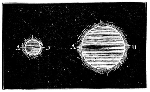
Fig. 64.—Images of planet produced by short and long focus lenses of the same aperture giving images of different size, but with the same amount of colour round the edges.
This matter requires a somewhat detailed treatment in order that it may be seen how the four surfaces to which reference has been made are determined.
The chromatic dispersion, in the case of the object-glass, may be roughly stated to be measured by about one fiftieth of the aperture. Suppose for instance the discs, Fig. 64, to represent the image of any object, say the 124planet Jupiter. Then round that planet we should have a coloured fringe, and the dimensions of that coloured fringe, that is, the joint thickness of colour at A and D, will be found by dividing the diameter of the object-glass used by fifty. Now this is absolutely independent of the focal length of the telescope; therefore one way of getting rid of it is to increase the focal length of telescopes; and as the size of the image depends on focal length, and has nothing whatever to do with aperture, we may imagine that with the same sized object-glass, instead of having a little Jupiter as on the left of Fig. 64, we may have a very large Jupiter, due to the increased focal length of the telescope. Then, it may be asked, how about the chromatic aberration? It will not be disturbed. The aperture of the object-glass remains unaltered, and there is no more chromatic aberration here than in the first case; so that the relation between the visible planet Jupiter and the colour round it is changed by altering the focal length. But as we have seen, we are able by means of a combination of flint and crown glass to counteract this dispersion to a very great extent. How then about spherical aberration?
Up to the present we have assumed that all rays falling on a convex lens are brought to a point or focus, but this is not strictly true, for the edges of a lens turn the rays rather too much out of their course, so that they will not come to a point; just as the rays reflected from a spherical mirror do not form a single focus. The marginal rays will be spread over a certain circular surface, just as the colour due to chromatic aberration covered a surface surrounding the focus. It was explained that for the same diameter of lens the circle of 125colour remained the same, irrespective of focal length, but in the case of spherical aberration this is not so; it diminishes as the square of the focal length increases; that is to say, if we double the focal length we shall not only halve, but half-halve, or quarter the aberration. Newton calculated the size of the circle of aberration in comparison with that due to colour, and he found that in the case of a lens of four inches diameter and ten feet focus, the spherical aberration was eighty-one and a half times less than that of colour. It is found that by altering the relative curvatures of the surfaces of the lens, this aberration can be corrected without altering the focal length; for any number of lenses can be made of different curvatures on each side but of the same thickness in the middle, so that they have all the same focal length, but the one, having one surface about three times more convex than the other, will have least aberration, so that it is the adaptation of the surfaces of lenses to each other that exercises the art of the optician.
So far we have got rid of this aberration in a single lens; it can also be done in the case of achromatic lenses. The foci of the two lenses in an achromatic combination must bear a certain relation to each other, and the curvatures of the surfaces must also have a certain relation for spherical aberration. In the achromatic lens there are four surfaces, two of which can be altered for one aberration and two for the other. For instance, in the case of the lens, Fig. 45, where the interior surfaces of the lenses are cemented together, although shown separate for clearness, we find that if the exterior surface of the crown double convex lens be of a curvature struck by a radius 672 units in length, and the exterior surface of the flint glass lens to a curvature due to a 126radius of 1,420 units, the lens will be corrected for spherical aberration, and these conditions leave the interior surfaces to be altered so that the relation between the powers of the lenses is such as to give achromatism.
The flint is as useful in correcting the spherical aberration as the chromatic aberration; for although the relative thicknesses of the flint and crown are fixed in order to get achromatism, still we have by altering both the curvatures of each lens equally, and keeping the same foci, the power of altering the extent of spherical aberration; and it is in the applications of these two conditions that much of the higher art of our opticians is exercised. We have now therefore practically got rid of both aberrations in the modern object-glass, and hence it is that lenses of the large diameter of twenty-five and twenty-six inches are possible.
The nearest approach to achromatism is known to be made when looking at a star of the first or second magnitude, the eyepiece being pushed out of focus towards the object-glass, the expanded disc has its margin of a claret colour. When the eyepiece is pushed beyond the focus outwards the margin of the expanded disc is of a light green colour.
If the object-glass is well corrected for spherical aberration, the expanded discs both within and without the focus will be constituted of a series of rings equally dense with regard to light throughout, with the exception of the marginal ring, which will be a little stronger than the rest.
Having determined the radius of curvature of surface, both he who grinds the speculum, whether of speculum metal or glass, and he who grinds the object-glass, starts 127fair; only one has four times the work to do that the other has. The grinding is managed in a simple way, and the process of grinding or polishing an object-glass or speculum, either of glass or of metal, is the same.
Supposing we wish to make a reflecting telescope of six feet focus, or a surface of an object-glass of twelve feet radius, all we have to do is to get a long rod, a little more than twelve feet long, and pin it to a wall at its upper end so that it can swing, pendulum fashion; then at a distance of twelve feet below the point of suspension a pin is stuck through the rod and its point made to scratch a line on a sheet of metal laid against the wall; then this line will be part of a circle struck with a radius of twelve feet. If then the plate be cut along this line we get a convex and a concave surface of the desired radius, and then we can take a block of iron or brass and turn its surface, convex or concave, to fit the sheet of metal or template. For a reflector we should make a convex tool, and for a refractor a concave one.
Generally this grinding tool is divided into squares or furrows all over it, in order that the emery which is used in rough grinding may flow freely about with the water. A disc of glass is then laid on the tool, or the tool on the glass, the two being pressed together by a weight or spring; emery powder, with water, is strewn between them, and one is rubbed over the other by a machine similar to those used for polishing, which we shall explain presently. This operation is continued until the glass is ground all over, and in this process of rough grinding the rough emery is used between the tool and the glass, so that whatever irregularities the glass or tool may have they are got rid of, and it is easy to obtain a spherical surface, and indeed, it is the only 128surface that can be obtained. Then finer and finer emery is used, till it ceases to be a sufficiently fine substance to use, and a surface of iron or lead is also too hard a surface. Now the polishing begins, and the optician and amateur avail themselves of a suggestion due to Sir Isaac Newton, who always saw much further through things than other people.

Fig. 65.—Showing in an exaggerated form how the edge of the speculum is worn down by polishing.
Even when he first began to make the first reflector, he used pitch, a substance not too hard, nor yet too soft, and one that can be regulated by temperature; therefore for polishing, instead of having a tool made of metal, pitch laid on glass or wood and supplied with rouge and water is used. This polisher of pitch is divided into squares by channels to allow free flow of rouge and water, and is laid on the mirror or object-glass, or vice versâ, and moved about over it.
When the maximum of polish is attained the work is done, and the object-glass finished, as here we have to do with a spherical surface. In the grinding of the two discs for Mr. Newall’s telescope 1,560 hours were consumed, the thickness of the crown disc having been reduced one inch in the process.
In the case of specula, however, there is more to be done; and it is in this polishing of specula that the curve is altered from a circle to a parabola by using a certain length of stroke, size of polisher, consistency of pitch, and numbers of other smaller matters, the 129proper proportionment of which constitutes the practical skill of the optician, and it is in accomplishing this that the finest niceties of manipulation come into play, and the utmost patience is required. 1,170 hours were occupied in the grinding and polishing of the four-feet Melbourne speculum. This was equivalent to 2,050,000 strokes of the machine at 33 per minute for rough and 24 for fine grinding. Dr. Robinson, in his description of the grinding operations, states that at the edge of one of the four-feet specula the distance of its parabola from the circle was only 0·000106˝.
In the early times of specula the polishing was invariably done by hand, a handle being cemented by pitch to the back of the speculum to work it with. Mudge tells us that at first, when the mirror was rough from the emery grinding, it was worked round and round on the pitch, which was supplied with rouge and water and cut by channels into small squares, carrying the edge but little over the polisher, an occasional cross stroke being made. The effect of this was to press the pitch towards the centre where the polish always commenced, and gradually spread to the circumference. As soon as the polishing was complete the speculum was worked by short straight strokes across the centre, tending to bring it back to a sphere; then the circular strokes were recommenced to restore the paraboloid form: these were continued for a short time only, otherwise it would pass the proper curve and require reworking with straight strokes again. By this method some small mirrors of first-class definition were constructed.
When Sir W. Herschel began his labours he constructed a machine for working the speculum over the 130polisher; the polisher was a little larger than the mirror, the proportion given by him from a number of trials being 1·06 to 1.
The speculum was held in a circular frame, which was free to turn round in another ring or frame; this frame was moved backwards and forwards by a vibrating lever to which it was attached by rods, carrying the speculum over the polisher. This motion he designates the stroke. Besides this there was the side motion produced by a rod attached to the side of the frame opposite to that to which the rods giving it the stroke were attached and at right angles to the direction of stroke: this rod was in connection, by means of intermediate levers, with a pin on a rachet wheel, which was turned a tooth at a time by a rod in connection with the lever giving the stroke motion, so that the rod giving the side motion was pushed and pulled back by the pin on the rachet wheel every time it turned round, which it did every twenty or thirty strokes. There were also teeth on the ring fastened round the edge at the back of the speculum, into which claws worked which were attached by rods to a point on the lever a little distance from the attachment of the rod giving the stroke, so that the claws had a less motion than the speculum and its ring, and consequently pulled the ring, and with it the speculum, round a tooth or more at each stroke. The polisher was also turned round in the same manner in a contrary direction to the motion of the speculum. The speculum had therefore three motions, a revolving one on its centre, a stroke, and a side motion, making its centre describe a number of parallel lines over the polisher on each side of its centre. Sir W. Herschel gives as a good working length of stroke, 0·29, and 0·19 side motion measured from 131side to side, the diameter of the speculum being 1. To produce a seven-inch mirror with this instrument he would work continuously for sixteen hours, his sister “putting the victuals by bits into his mouth.”

Fig. 65*.—Section of Lord Rosse’s polishing machine.
Lord Rosse adopted a similar arrangement; the polisher, K L, Fig. 65, was worked over the speculum in straight strokes with side motion, the requisite straight motion being given by a crank-pin and rod and the side motion by the continuation of this latter rod on the other side of the polisher working in a guide on another crank-pin, which threw it from side to side as the wheel carrying the pin revolved. The trough E F carrying the speculum also revolved slowly, and the requisite motions were given by pulleys and straps of various sizes under the table on which the machine rested; the weight of the polisher was in a great measure counterpoised by strings from its upper surface to a weighted lever M above. The polisher was free to turn in its ring, which it did once in about twenty strokes, and for the six feet speculum the velocity of working was about eight strokes a minute, the length of stroke being one-third of the diameter of the speculum, and that of the side motion one-fifth.
The speculum was polished on the same system of 132levers that were afterwards to support it, in order that no change of form might be produced in moving it to a different mounting. The consistency of the pitch is a matter of importance, Mr. Lassell’s test of the requisite hardness being the number of impressions left by a sovereign standing on edge on it; this should leave three complete impressions of the milled edge in one minute at the ordinary temperature of the atmosphere.
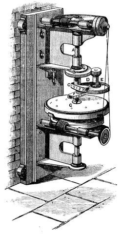
Fig. 66.—Mr. Lassell’s polishing machine.
Fig. 66 represents the machine contrived by Mr. Lassell for his method of polishing, and shows what 133a complicated arrangement is essential in order to arrive at any good result in these matters.
The speculum is placed on a bed, and above it is a train of wheels terminating in a crank-pin that gives motion to the polisher, which is made to take a very devious path by the motion of the wheels above. The pin giving motion to the polisher G at its centre can be set at a variable distance from the axis of the lowest pinion F to which it is attached, by moving it in its slide, so that when the pinion is turned, the pin and centre of the polisher describe a circle. The pinion in question is carried on a slide C above it, attached to the main vertical driving shaft A, so that as the shaft revolves the centre of the pinion describes a circle of a diameter variable at pleasure by moving it in the slide C, the result of the two motions being that the centre of the polisher describes circles about a moving centre, and consequently in constantly varying positions on the speculum. Motion is given to the vertical shaft by the cog-wheel and endless screw above, worked by some prime mover, and as the cogwheels on the shaft E parallel to the main shaft are carried round the latter by the arm D holding them, they are caused to revolve by gearing into the fixed wheel B, through the centre of which the main shaft passes, and they in their turn impart motion to the pinion carrying the pin giving motion to the polisher. The speculum is also maintained in slow rotation by the wheel and endless screw below it. The speculum and its supports are surrounded by water contained in a circular trough not shown in the engraving, so that the consistency of the pitch shall be constant.
This arrangement, pure and simple, was found to bring on the polish in rings over the speculum, and as an 134improvement, the speculum, or rather the system of levers supporting it, was carried on a plate which had the power of sliding backwards and forwards on the wheel turning it round; the edges of this plate pressed against a fixed roller, and it was made of such a shape that as it revolved it was forced to take a side motion as its edges passed by the fixed roller, so that the speculum had a side motion in addition to the rotatory one.
Mr. De La Rue improved on this by giving the speculum a rotatory motion irrespective of that of the sliding plate, so that the side motion should not always be along the same diameter of the speculum. This was done by allowing the speculum to turn freely on a pivot on the sliding plate, and giving it a rotatory motion by means of a cord going round the plate carrying the speculum supports. As a further improvement Mr. De La Rue controls the motion of the polisher on the central pin, giving it motion by a crank carrying a system of wheels in place of the lowest crank, so that the pin gets a rotatory motion in addition to these.
Mr. Grubb’s arrangement for polishing is different. The speculum is made to rotate, the polisher is made to execute curves variable at pleasure by altering the throw of the cranks which move rods attached to the centre of the polisher, giving it a motion similar to that of Mr. Lassell’s machine. The polisher moves a little off the edge, so that the edge is worn down more than the centre, thus giving the parabolic form.
M. Foucault, of whom we have already spoken, proceeds in a different manner in parabolising his glass mirrors. He first obtains a spherical surface, fairly reflective, by grinding. He then alters the surface to a paraboloid form by handwork, only testing the surface from 135time to time to ascertain the parts requiring reduction by the polishing pad. The method of testing is as beautiful as it is simple. The approximate estimate of the curvature of the speculum is made by placing a small and well-defined object, such as the point of a pin, close to the centre of curvature and examining its image formed close by its side with a lens. As a nicer test, he places an object having parallel sides, say a flat ruler, near the centre of curvature, and views its image with the naked eye at the distance of distinct vision, then each point of the edge is seen by rays converging only from a small portion of the surface of the mirror, the remainder of the diverging cone from each point of the edge passes on beside the eye, and by moving the eye about, any point of the edge can be seen formed by rays proceeding from any particular part of the mirror, viz., that part in line with the eye and point of the edge examined; if the curvature be not uniform the edge will appear distorted, and points on it will appear in different positions, as rays from different parts of the mirror are received by the eye as it is moved, making the edge appear to move in waves. Finally, he allows light from a very small hole in a metal plate near the centre of curvature to fall on the mirror, and places the eye just on the side opposite to the point where the image is formed, so as to receive the rays as they diverge after having come to a focus. The whole of the light thus passes into the eye, and the mirror is seen illuminated in every part. A sharp edge of metal is then gradually brought into the focus, when the illumination of the mirror decreases, and just before the light disappears the irregularities will plainly appear, showing themselves by patches of light, which prove that those parts still bright are so inclined as to reflect the rays 136by the side of the true focus. By moving the metallic edge so as to advance upon the focus from all sides, a very good idea of the irregularities may be obtained. If, however, the surface be truly spherical, the light will disappear regularly over the whole surface.
M. Foucault commences by making the surface truly spherical, and then by polishing off in concentric circles, increasing the polishing from the centre, an elliptic and at last a parabolic curve is attained. The ellipse is tested from time to time by removing the perforated plate further and further away from the mirror until the ellipse becomes practically a parabola. The great advantage of this method is, that the effect of the polishing can be examined as it proceeds, and the work can always be applied wherever necessary, and the test is entirely independent of hot-air currents which are seen to fluctuate over the mirror as waves of light, leaving the irregularities of form permanently marked. It further appears that the method may be varied to form a first-rate test of a finished mirror already mounted; for one has nothing to do but bring a star into the field of view, and remove the eyepiece, and bring the eye into such a position as to receive the diverging rays from the focus of the star. A knife is then gradually moved across in front of the eye, say from the right; then if the mirror commences to get darkened on the right side distinctly before the left the knife is on the mirror side of the focus; if, however, the left side of the mirror becomes darkened first it is on the eye side of the focus. After a few trials it can be got to cut across the focus and darken the mirror at all points at once, and show up all irregularities.
We have now, then, by one system or another, got our mirror, either of speculum metal or of glass, and if of the 137latter substance we have to silver it; processes have been published by Mr. Browning, and M. Martin,[7] by which, on the plan proposed in the first instance by Liebig, an extremely thin coating of silver is deposited on the glass. This film is susceptible of taking a high polish, which, in the case of small mirrors, can be renewed as often as is wished without repolishing the mirror; the resilvering of one of large aperture however is a most 138formidable affair. To those who wish to silver their own mirrors, let us say that it should be done in summer, or in a room kept by a stove at an equable summer heat, and the silvering solution should be kept for a day or more to settle, and for probably some chemical change to take place before the reducing solution is added. It will be found easy enough to silver the small planes for Newtonian reflectors, but large mirrors require much greater care and trouble.
6. Professor Stokes and Mr. Vernon Harcourt some time ago made experiments with phosphatic glass, and some of this material was worked into a lens by Mr. Grubb, who states that “the result was successful so far as the obtaining of specimens of phosphatic glass with rational spectra; but phosphatic glass is almost unworkable, and when the experiment was tried on a siliceous glass it failed. Some alleviation of this secondary spectrum can be got by using a triple objective, but with, of course, a corresponding loss of light.”
7. Mr. Browning’s method of silvering glass specula is as follows:—
Prepare three standard solutions:
| Solution A | { | Crystals of nitrate of silver | 90 | grains | } | Dissolve. |
| { | Distilled water | 4 | ounces | } | ||
| Solution B | { | Potassa, pure by alcohol | 1 | ounce | } | Dissolve. |
| { | Distilled water | 25 | ounces | } | ||
| Solution C | { | Milk-sugar (in powder) | ½ | ounce | } | Dissolve. |
| { | Distilled water | 5 | ounces | } |
Solutions A and B will keep, in stoppered bottles, for any length of time; Solution C must be fresh. To prepare sufficient for silvering an 8 in. speculum, pour two ounces of Solution A into a glass vessel capable of holding thirty-five fluid ounces. Add, drop by drop, stirring all the time (with a glass rod), as much liquid ammonia as is just necessary to obtain a clear solution of the grey precipitate first thrown down. Add four ounces of Solution B. The brown-black precipitate formed must be just re-dissolved by the addition of more ammonia, as before. Add distilled water until the bulk reaches fifteen ounces, and add, drop by drop, some of Solution A, until a grey precipitate, which does not re-dissolve after stirring for three minutes, is obtained; then add fifteen ounces more of distilled water. Set this solution aside to settle; do not filter. When all is ready for immersing the mirror, add to the silvering solution two ounces of Solution C, and stir gently and thoroughly. Solution C may be filtered.
The mirror should be suspended face downwards about ½-inch deep in the liquid, by strings attached to pieces of wood fastened to the back of the mirror with pitch, and before being immersed should be cleaned with nitric acid and washed with distilled water. The silvering is completed in about an hour, and when finished the surface should be washed in distilled water and dried, and then polished with soft leather, finishing with a little rouge.
The following method is used by M. Martin:—
Make solutions:
| 1. | Nitrate of silver | 4 | per cent. | ||
| 2. | Nitrate of ammonia | 6 | per cent. | } | perfectly free |
| 3. | Caustic potash | 10 | per cent. | } | from carbonates. |
4. Dissolve twenty-five grammes of sugar in 250 grammes of water; add three grammes of tartaric acid; heat it to ebullition during ten minutes to complete the conversion of sugar; cool down, and add fifty cubic centimetres of alcohol in summer to prevent fermentation, add water to make the volume to ½ litre in winter and more in summer.
Clean well the surface of the glass.
Take equal quantities of the four solutions: mix 1 and 2 together, and 3 and 4 also together: mix the two, pouring it at once into the vessel where the silvering is to be done. The mirror is suspended face downwards in the liquid, and the deposit begins after about three minutes, and is finished after twenty minutes. Take out the mirror, clean well with water, dry it in the air, and rub it then gently with a very fine leather.
Having now obtained the lenses and specula we come, in order to complete our consideration of the purely optical portion of the subject, to the question of mounting these lenses and specula in tubes and thus connecting them with the eyepieces so as to become of practical utility. We will first consider the adjustment of lenses in a tube, the combination forming a simple telescope that can be supported, in any manner desirable, by mountings we shall presently consider, according to the purpose for which it is required. The adjustment of specula will be considered as we advance further.
The smaller telescopes consist of a brass tube, the object-glass, held in a brass ring, being screwed in at one end of the tube: a smaller tube sliding in and out of the other end of the large tube, generally moved by a rack and pinion motion, carries the eyepiece. In larger telescopes the mounting is similar, only somewhat more elaborate, the object-glass being carried in a brass cell, or a steel one if the dimensions are very large. This screws into the ring at the end of the tube, and this ring can be slightly tipped on either side by set screws, so that the object-glass can be brought exactly at right angles to the axis of the tube.

Fig. 67.—Simple telescope tube, showing arrangement of object-glass and eyepiece.
It is important, in order that an object-glass shall perform its best, that the lenses forming it shall be properly centred: this is generally done by the maker once and for ever. Wollaston pointed out an ingenious method of centring them; it is as follows:—The eyepiece is removed, and a lighted candle put in its place: the object-glass is then examined from the opposite side, when, if all the lenses are correctly placed, the images of the candle produced by the successive reflections of the candle from the surfaces of the lenses will be concentric, and in a straight line from the candle through the centre of the system of lenses, a fact easily judged of, by moving the eye slightly from side to side, and if they are not, they are easily corrected by tipping the lens in fault slightly in the cell. In case the lenses are cemented together, this method of course is applicable in setting the object-glass at right angles to the axis of the tube. The adjustment of an object-glass can also be judged of by examining a star as it is thrown in and out of focus by the focusing screw; the disc of the star should be perfectly round in and out of focus, and the rings produced by interference should also be circular when in focus, and the disc of light, when out of focus, must be circular. Any elongation of the disc or rings, or a “flare” appearing, shows a want of a slight alteration of the setting screw, on the same side of the object-glass as the “flare” or elongation appears.
141In some object-glasses the curves of the two interior surfaces are such that three pieces of tin foil are placed at equal distances round the edge to prevent the central portions from coming in contact.
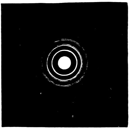
Fig. 68.—Appearance of diffraction rings round a star when the object-glass is properly adjusted.
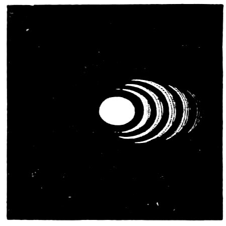
Fig. 69.—Appearance of same object when object-glass is out of adjustment.
The flexure of small object-glasses by their own weight is of little importance, because every surface is affected alike; but when the aperture is large special precautions have to be taken. The late Mr. Cooke when he had completed the 25-inch object-glass for Mr. Newall’s telescope, introduced a system of counterpoise levers just within the edge which helped to support the object-glass in all positions. Mr. Grubb states that with an aperture of 15 inches, supported on three points, there is decided evidence of flexure, and he proposes, in the 27-inch Vienna refractor, not only to introduce six intermediate supports, thereby following in the footsteps of Mr. Cooke, but with larger apertures to introduce boldly a central support, or to hermetically seal the tube and fill it with compressed air. He has calculated that in the case of an object-glass 40 inches aperture, weighing 600 lbs., two-thirds of its weight could be supported by an air pressure of one-third of a pound to the square inch.
142The tube of the telescope when of large size is usually made of iron or wood, and a tube of the latter substance may be made very light and yet sufficiently strong, by wrapping layers of veneer round a central core and fastening the layers firmly with glue. There are generally two or more tubes sliding inside each other at the eye end of the telescope, to carry the eyepiece so as to give plenty of power of adjustment of the length of the tube to suit the different eyepieces, or other instruments used in their place. The tube then is ready to be adapted to any of the mountings to be hereafter considered.
We now come to the mounting of specula, and when we recollect the enormous weights of some of the specimens to which we have referred, it will be obvious that some additional precautions, which are not at all necessary in the case of a refractor, must be taken to insure success.
In reflecting telescopes, the speculum is carried at the bottom of a tube in a sort of tray or cell, which can be adjusted by screws at the back, so as to set the mirror at right angles to the tube, and the conditions of support should be such that the mirror should be as free from strain as if it were floating in mercury. A system of lateral supports in all positions is also necessary.
The action of the telescope depends greatly on the backing of the speculum, and numerous methods of carrying specula on soft backing and systems of levers have been suggested, all aiming at carrying them so that they are free from all possible strain and flexure occasioned by their own weight. For smaller mirrors a soft back of flannel or cloth can be used, and a leather strap placed round the mirror and its back, so as to form 143the side of a sort of circular tray, will give it sufficient support when inclined to the horizontal. Mr. Browning adopts the plan of making the back of the mirror and its support perfectly flat, so as not to require levers or soft backing; this arrangement would probably fail for mirrors larger than one foot in diameter, although answering admirably for those of less size.

Fig. 70.—Optical part of a Newtonian reflector of ten inches aperture, showing eyepiece, adjusting screws for large speculum, finder, door for uncovering speculum, and counterpoise.

Fig. 71.—Optical part of Melbourne reflector, showing the lattice arrangement for supporting the convex mirror Y, T more solid part of tube fixed to declination axis, W finder.
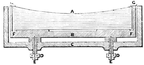
Fig. 72. Mr. Browning’s method of supporting small specula. The bottom of the speculum A is a carefully prepared plane surface, and the outer rim of the inner iron cell B, on which it rests, is also a plane. The speculum is kept in this cell by the ring G G, and it may be removed from, and replaced in, the telescope, without altering its adjustment.
We will now consider the methods of mounting specula of larger size, and will take as an instance the mounting of some of the largest specula in existence which must act so as to prevent flexure in any position of the speculum. The speculum is, in the case of the Melbourne telescope, of the weight of something like two tons. When it is inclined at any considerable angle to the horizon, it is apt to bend over at the top, and thus destroy its proper curvature; and when horizontal, if not equally supported, it will also bend, and unless some measures are taken to prevent this flexure it will so entirely alter its figure by its own weight as to render minute observations of any delicate stars absolutely impossible.
Mr. Lassell was the first to suggest an arrangement for preventing this flexure. Through the back of the speculum case—the case which holds and supports the 145speculum, which we shall have to speak about presently—he inserts a large number of very small levers, the centres of which are fixed to the exterior part of this case, the forward part of each resting against a small aperture made in the back of the speculum. The ends of the levers furthest from the speculum are crowned with small weights, the weights varying on different parts of the speculum. Now so long as the speculum is perfectly horizontal, i.e. so long as the zenith is being observed, these levers will have no action whatever; but the moment the reflector is brought into any other position, as, for instance, when we wish to observe a star near the horizon, the more the mirror is inclined to the horizon the greater will be the power of these small levers, and at length their total effect comes into action when a star close to the horizon is being observed. Then the whole weight of the mirror is carried by these levers acting at points all over its back.
In the Melbourne reflector, which has recently been finished, Mr. Grubb manages this somewhat differently, as will be seen by Figs. 73-76.
In Fig. 73 the speculum is in a vertical position. It is supported in a frame, B B, all round it, which consists of a slightly flexible hoop of metal a little larger than the speculum. This in its turn is supported by a large fixed hoop, A A, having a hook-shaped section. This hoop is attached to the tube of the telescope C C. The hoop, B B, is rather larger than the part of A on which it hangs, so that it can adjust itself to the form of the mirror; and not only is the mirror supported in the hoop B B, like as in a strap in the position shown, but in every other position of the tube the speculum still hangs evenly supported.
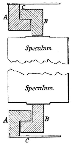
Fig. 73.—Support of the mirror when vertical.
As we have already seen, there is another point to consider. Not only must we be able to support the mirror when inclined to the horizon, but we must support it bodily at the end of the tube when it is horizontal. We will next examine an arrangement adopted by Mr. Grubb, similar to that adopted by others, for supporting the Melbourne speculum, and we cannot do better than quote Mr. Grubb’s own explanation of it. He says:—
“To understand it, suppose the speculum to be divided into forty-eight portions, as in Fig. 74, each of them being exactly equal in area, and consequently in weight. Now, if the centre of gravity of each of these pieces rested on points which would bear up with a force = the weight of each segmental piece, it is evident that there would be no strain in the mass from segment to segment.
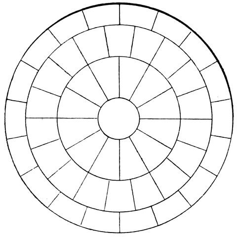
Fig. 74.—Division of the speculum into equal areas.
“This is exactly what is accomplished by this system; in fact, if when the speculum is resting on these supports it could be divided up into segments corresponding to those lines, they would have no inclination to leave their places, showing a perfect absence of strain across those lines. Suppose now the points representing the centres of gravity of these segments were supported on levers and triangles, so as to couple them together, as at A, Fig. 75, and each of these couplings to be supported from a point a, representing the centre of gravity of the sum of the segments supported by that particular couple, and it is evident that there can be no strain between the components of these couples. Again, let these points, a, be coupled together by the system shown at B, Fig. 75, and their centres of gravity, b, coupled as at C, and it is evident that the whole weight of the speculum ultimately condensed by this system into these points is supported on forty-eight points of equal support being the centres of gravity of the forty-eight segments at Fig. 75. In Fig. 76 is seen the whole system complete. It consists of three screws passing through the back of the speculum 148box (which serve for levelling the mirror), the points of which carry levers (primary system) supporting triangles on their extremities (secondary system), from the vertices of which are hung two triangles and one lever (tertiary system). All the joints of this apparatus are capable of a small rocking motion, to enable them to take their positions when the speculum is laid upon them.
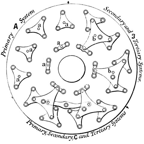
Fig. 75.—Primary, secondary, and tertiary systems of levers shown separately.
Fig. 76.—Complete system consolidated into three screws.
“In the system of levers made by Lord Rosse for his six-feet speculum, the primary, secondary, and tertiary systems were piled up one over the other, so that the distance from the support of the primary to the back of the speculum was about fifteen inches. This, as will be readily seen on consideration, introduced a new strain when the telescope was turned off the zenith, and had to be counterpoised by another very complicated system of levers. But in the Melbourne telescope, by the substitution of cast-steel for cast-iron, and by hanging the tertiary system from the secondary, and allowing it (the tertiary) to act in some places through the secondary, the whole system is reduced to three and a half inches 149in height, and the distance from the support of the primary lever to the back of the speculum is only one and three-quarter inch, by which means this cumbersome apparatus is entirely done away with.
“The ultimate points of the tertiary system are gunmetal cups, which hold truly ground cast-iron balls with a little play, and when the speculum is laid on these it can be moved about a little by a person’s finger with such ease as to seem to be floating in some liquid.”
It may perhaps be thought that it would be better to support these great specula on a flat surface, and it might be, if we could do so without extreme difficulty; but Lord Rosse has stated that if we attempt to support a large speculum on a surface extremely flat, a thread placed across that surface, or even a piece of dust, is quite enough to bend the mirror and render it absolutely useless. That will show the extreme importance of the support of the speculum.
Let us then assume that we have the speculum and the tube perfectly adjusted. The next thing, in all constructions except the Herschelian, is to apply the second small reflector, concave in the case of the Gregorian, convex in the case of the Cassegrainian, and plane in the case of the Newtonian.
This small mirror is generally supported by a thin strip of metal firmly fastened to the side of the tube, with power of movement parallel to the axis of the telescope, in the case of the Gregorian and Cassegrainian, for the purpose of focussing. In the Newtonian, the reflecting diagonal prism or plane mirror, inclined at an angle of 45° to the axis, is preferably supported in the manner suggested by Mr. Browning. See Figs. 77 and 78.
In these B B B represent strips of strong chronometer 150spring steel, placed edgewise towards the speculum; by these the prism or small mirror D is suspended.
The mirror thus mounted, does not produce such coarse rays on bright stars as when it is fixed to a single stout arm; it is also less liable to vibration, which is very injurious to distinct vision, or to flexure, which interferes with the accuracy of the adjustments.
Fig. 77.—Support of diagonal plane mirror (Front view).
Fig. 78.—Support of diagonal plane mirror (Side view).
The most usual form of reflector is the Newtonian, large numbers of which kind are now made; and just as the object-glasses of refractors require adjusting, so do not only the large mirror, but also the “flat” or diagonal mirror of this form. In the Newtonian the flat must be adjusted first; to do this, first place the large mirror in its cell in the tube, and secure it by turning it in the bayonet joint, with the cover on the mirror. Then remove the glasses from one of the eyepieces, insert it into the eyetube, and fix the diagonal mirror loosely in its position.
Then, looking through the eyetube, move the diagonal mirror, by means of the motions which are provided, until the reflected image of the cover of the speculum is seen in the centre of it.
151This is accomplished by first loosening the milled-headed screw behind the mirror, and turning the mirror until the image of the speculum cover appears central in one direction. The screw at the back of the mirror enables the reflected image to be brought central in the other direction.
Next comes the turn of the large mirror. Take off the cover by screwing off the side opening and place the eye at the eyetube after having removed the eyepiece; the reflection of the diagonal mirror will be seen in the reflected image of the speculum. The adjusting screws, at the back of the speculum, must then be moved until the diagonal mirror is seen in the centre of the speculum. The adjustment should then be complete.
This may be judged of by bringing a star to the centre of the field, and sliding the focussing-tube in or out, when the circle of light should expand equally, and its centre should remain central in the field. As another test a bright star should be viewed with a high power, and the image examined; if it is round and the circles of light round it are concentric without rays in any one direction, then all is correct; but if a flare is seen, it is evidence that the part of the diagonal mirror towards which the flare extends must be moved from the eye by the setting-screws at the back.
The gain to astronomy from the discovery of the telescope has been twofold. We have first, the gain to physical astronomy from the magnification of objects, and secondly, the gain to astronomy of position from the magnification, so to speak, of space, which enables minute portions of it to be most accurately quantified.
Looking back, nothing is more curious in the history of astronomy than the rooted objection which Hevel and others showed to apply the telescope to the pointers and pinnules of the instruments used in their day; but doubtless we must look for the explanation of this not only in the accuracy to which observers had attained by the old method, but in the rude nature of the telescope itself in the early times, before the introduction of the micrometer. We shall show in a future chapter how the modern accuracy has step by step been arrived at; in the present one we have to see what the telescope does for us in the domain of that grand physical astronomy which deals with the number and appearances of the various bodies which people space.
Let us, to begin with, try to see how the telescope helps us in the matter of observations of the sun. The 153sun is about ninety millions of miles away; suppose, therefore, by means of a telescope reflecting or refracting, whichever we like, we use an eyepiece which will magnify say 900 times, we obviously bring the sun within 100,000 miles of us; that is to say, by means of this telescope we can observe the sun with the naked eye as if it were within 100,000 miles of us. One may say, this is something, but not much; it is only about half as far as the moon is from us. But when we recollect the enormous size of the sun, and that if the centre of the sun occupied the centre of our earth the circumference of the sun would extend considerably beyond the orbit of the moon, then one must acknowledge we have done something to bring the sun within half the distance of the moon. Suppose for looking at the moon we use on a telescope a power of 1,000, that is a power which magnifies a thousand times, we shall bring the moon within 240 miles of us, and we shall be able to see the moon with a telescope of that magnifying power pretty much as if the moon were situated somewhere in Lancashire—Lancaster being about 240 miles from London.
It might appear at first sight possible in the case of all bodies to magnify the image formed by the object-glass to an unlimited extent by using a sufficiently powerful eyepiece. This, however, is not the case, for as an object is magnified it is spread over a larger portion of the retina than before; the brightness, therefore, becomes diminished as the area increases, and this takes place at a rate equal to the square of the increase in diameter. If, therefore, we require an object to be largely magnified we must produce an image sufficiently bright to bear such magnification; this means that we must use an object-glass or 154speculum of large diameter. Again, in observing a very faint object, such as a nebula or comet, we cannot, by decreasing the power of the eyepiece, increase the brightness to an unlimited extent, for as the power decreases, the focal length of the eyepiece also increases, and the eyepiece has to be larger, the emergent pencil is then larger than the pupil of the eye, and consequently a portion of the rays of the cone from each point of the object is wasted.
Fig. 79.—A portion of the constellation Gemini seen with the naked eye.
We get an immense gain to physical astronomy by the revelations of the fainter objects which, without the telescope, would have remained invisible to us; but, as we know, as each large telescope has exceeded preceding ones in illuminating power, the former bounds of the visible creation have been gradually extended, though even now we cannot be said to have got beyond certain small limits, for there are others beyond the region which the most powerful telescope reveals to us; though we have got only into the surface we have increased the 3,000 or 6,000 stars visible to the naked eye to something like twenty millions. This space-penetrating power of the telescope, as it is called, depends on the principle that whenever the image formed on the retina is less than sufficient to appear of an appreciable size the light is apparently spread out by a purely physiological action until the image, say of a star, appears of an appreciable diameter, and the effect on the retina of such small points of light is simply proportionate to the amount of light received, whether the eye be assisted by the telescope or not; the stars always, except when sufficiently 155bright to form diffraction rings, appearing of the same size. It, therefore, happens that as the apertures of telescopes increase, and with them the amount of light, (the eyepieces being sufficiently powerful to cause all the light to enter the eye,) smaller and smaller stars become visible, while the larger stars appear to get brighter and brighter without increasing in size, the image of the brightest star with the highest power, if we neglect rays and diffraction rings, being really much smaller than the apparent size due to physiological effects, and of this latter size every star must appear.
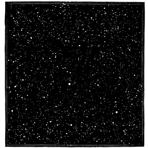
Fig. 80.—The same region, as seen through a large telescope.
156The accompanying woodcuts of a region in the constellation of Gemini as seen with the naked eye and with a powerful telescope will give a better idea than mere language can do of the effect of this so-called space-penetrating power.
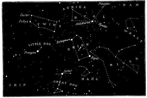
Fig. 81.—Orion and the neighbouring constellations.
With nebulæ and comets matters are different, for these, even with small telescopes and low powers, often occupy an appreciable space on the retina. On increasing the aperture we must also increase the power of the eyepiece, in order that the more divergent cones of light from each point of the image shall enter the pupil, and therefore increase the area on the retina, over which the increased amount of light, due to greater aperture, is spread; the brightness therefore is not increased, unless indeed we 157were at the first using an unnecessary high power. On the other hand, if we lengthen the focus of the object-glass, and increase its aperture, the divergence of the cones of light is not increased and the eyepiece need not be altered, but the image at the focus of the object-glass is increased in size by the increase of focal length, and the image on the retina also increases as in the last case. We may, therefore conclude that no comet or nebula of appreciable diameter, as seen through a telescope having an eyepiece of just such a focal length as to admit all the rays to the eye, can be made brighter by any increase of power, although it may easily be made to appear larger.
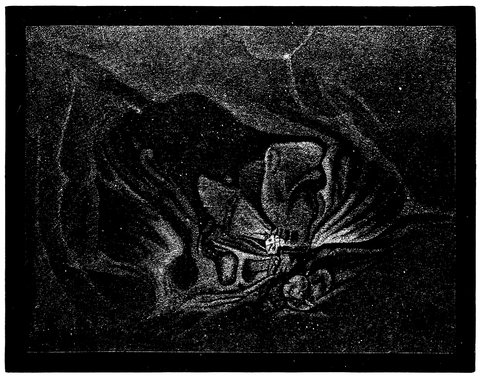
Fig. 82.—Nebula of Orion.
158Very beautiful drawings of the nebula of Orion and of other nebulæ, as seen by Lord Rosse in his six-foot reflector, and by the American astronomers with their twenty-six inch refractor, have been given to the world.
The magnificent nebula of Orion is scarcely visible to the naked eye; one can just see it glimmering on a fine night; but when a powerful telescope is used, it is by far the most glorious object of its class in the Northern hemisphere, and surpassed only by that surrounding the variable star η Argûs in the Southern. And although, of course, the beauty and vastness of this stupendous and remote object increase with the increased power of the instrument brought to bear upon it, a large aperture is not needed to render it a most impressive and awe-inspiring object to the beholder. In an ordinary 5-foot achromatic, many of its details are to be seen under favourable atmospheric conditions.
Those who are desirous of studying its appearance, as seen in the most powerful telescopes, are referred to the plate in Sir John Herschel’s “Results of Astronomical Observations at the Cape of Good Hope,” in which all its features are admirably delineated, and the positions of 150 stars which surround θ in the area occupied by the Nebula, laid down. In Fig. 82 it is represented in great detail, as seen with the included small stars, all of which have been mapped with reference to their positions and brightness. This then comes from that power of the telescope which simply makes it a sort of large eye. We may measure the illuminating power of the telescope by a reference to the size of our own eye. If one takes the pupil of an ordinary eye to be something like the fifth of an inch in diameter, which in some cases is an 159extreme estimate, we shall find that its area would be roughly about one-thirtieth part of an inch. If we take Lord Rosse’s speculum of six feet in diameter the area will be something like 4,000 inches: and if we multiply the two together we shall find, if we lose no light, we should get 120,000 times more light from Lord Rosse’s telescope than we do from our unaided eye, everything supposed perfect.
Let us consider for a moment what this means; let us take a case in point. Suppose that owing to imperfections in reflection and other matters two-thirds of the light is lost so that the eye receives 40,000 times the amount given by the unaided vision, then a sixth magnitude star—a star just visible to the naked eye—would have 40,000 times more light, and it might be removed to a distance 200 times as great as it at present is and still be visible in the field of the telescope, just as it at present is to the unaided eye. Can we judge how far off the stars are that are only just visible with Lord Rosse’s instrument? Light travels at the rate of 185,000 miles a second, and from the nearest star it takes some 3½ years for light to reach us, and we shall be within bounds when we say that it will take light 300 years to reach us from many a sixth magnitude star.
But we may remove this star 200 times further away and yet see it with the telescope, so that we can probably see stars so far off that light takes 60,000 years to reach us, and when we gaze at the heavens at night we are viewing the stars not as they are at that moment, but as they were years or even hundreds of years ago, and when we call to our assistance the telescope the years become thousands and tens of thousands—expressed in 160miles these distances become too great for the imagination to grasp; yet we actually look into this vast abyss of space and see the laws of gravitation holding good there, and calculate the orbit of one star about another.
Whether the telescope be of the first or last order of excellence, its light-grasping powers will be practically the same; there is therefore a great distinction to be drawn between the illuminating and defining power. The former, as we have seen, depends upon size (and subsidiarily upon polish), the latter depends upon the accuracy of the curvature of the surface.
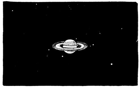
Fig. 83.—Saturn and his moons (general view with a 3¾-inch object-glass.)
If the defining power be not good, even if the air be perfect, each increase of the magnifying power so brings out the defects of the image, that at last no details at all are visible, all outlines are blurred, or stellar character is lost.
The testing of a glass therefore refers to two different qualities which it should possess. Its quality as to material and the fineness of its polish should be such that the maximum of light shall be transmitted. Its quality, as to the curves, should be such that the rays passing through every part of its area shall converge absolutely to the same point, with a chromatic aberration 161not absolutely nil, but sufficient to surround objects with a faint violet light.
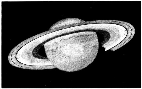
Fig. 84.—Details of the ring of Saturn observed by Trouvelot with the 26-inch Washington Refractor.
162In close double stars therefore, or in the more minute markings of the sun, moon, or planets, we have tests of its defining power; and if this is equally good in the instruments examined, the revelations of telescopes as they increase in power are of the most amazing kind.
A 3¾-inch suffices to show Saturn with all the detail shown in Fig. 83, while Fig. 84 shows us the further minute structure of the rings which comes out when the planet is observed with an aperture of 26 inches.
In the matter of double stars, a telescope of 2 inches aperture, with powers varying from 60 to 100, should show the following stars double:—
| Polaris. | |
| α | Piscium. |
| μ | Draconis. |
| γ | Arietis. |
| ρ | Herculis. |
| ζ | Ursæ Majoris. |
| α | Geminorum. |
| γ | Leonis. |
| ξ | Cassiopeæ. |
A 4-inch aperture, powers 80-120, reveals the duplicity of—
| β | Orionis. |
| ε | Hydræ. |
| ε | Boötis. |
| ι | Leonis. |
| α | Lyræ. |
| ξ | Ursæ Majoris. |
| γ | Ceti. |
| δ | Geminorum. |
| σ | Cassiopeæ. |
| ε | Draconis. |
A 6-inch, powers 240-300—
| ε | Arietis. |
| 32 | Orionis. |
| λ | Ophiuchi. |
| 20 | Draconis. |
| κ | Geminorum. |
| ι | Equulei. |
| ξ | Herculis. |
| ξ | Boötis. |
An 8-inch—
| δ | Cygni. |
| γ2 | Andromedæ. |
| Sirius. | |
| 19 | Draconis. |
| μ2 | Herculis. |
| μ2 | Boötis. |
163The “spurious disk,” which a fixed star presents, as seen in the telescope, is an effect which results from the passage of the light through the object-glass; and it is this appearance which necessitates the use of the largest apertures in the observation of close double stars, as the size of the star’s disk varies, roughly speaking, in the inverse ratio of the aperture of the object-glass.
In our climate, which is not so bad as some would make it, a 6- to an 8-inch glass is doubtless the size which will be found the most constantly useful; a larger aperture being frequently not only useless, but hurtful. Still, 4 or 3¾ inches are apertures by all means to be encouraged; and by object-glasses of these sizes, made of course by the best makers, views of the sun, moon, planets, and double stars may be obtained, sufficiently striking to set many seriously to work as amateur observers, and with a prospect of securing good, useful results.
Observations should always be commenced with the lowest power, gradually increasing it until the limit of the aperture, or of the atmospheric condition at the time, is reached. The former may be taken as equal to the number of hundredths of inches which the diameter of the object-glass contains. Thus, a 3¾-inch object-glass, if really good, should bear a power of 375 on double stars where light is no object; the planets, the Moon, &c., will be best observed with a much lower power. (See chapter on eyepieces.)
Care should be taken that the object-glass is properly adjusted. And we may here repeat that this may be done by observing the image of a large star out of focus. If the light be not equally distributed over the image, or the diffraction rings are not circular, the screws of the 164cell should be carefully loosened, and that part of the cell towards which the rings are thrown very gently tapped with wood, to force it towards the eyepiece, or the same purpose may be effected by means of the setscrews always present on large telescopes, until perfectly equal illumination is arrived at. This, however, should only be done in extreme cases; it is here especially desirable that we should let well alone.
The convenient altitude at which Orion culminates in these latitudes renders it particularly eligible for observation; and during the first months of the year our readers who would test their telescopes will do well not to lose the opportunity of trying the progressively difficult tests, both of illuminating and separating power, afforded by its various double and multiple systems, which are collected together in such a circumscribed region of the heavens that no extensive movement of their instruments—an important point in extreme cases—will be necessary.
Beginning with δ, the upper of the three stars which form the belt, the two components will be visible in almost any instrument which may be used for seeing them, being of the second and seventh magnitudes, and well separated. The companion to β, though of the same magnitude as that to δ, is much more difficult to observe, in consequence of its proximity to its bright primary, a first-magnitude star. Quaint old Kitchener, in his work on telescopes, mentions that the companion to Rigel has been seen with an object-glass of 2¾-inch aperture; it should be seen, at all events, with a 3-inch. ζ, the bottom star in the belt, is a capital test both of the dividing and space-penetrating power, as the two bright stars of the second and sixth magnitudes, of 165which the close double is composed, are exactly 2½˝ apart, while there is a companion to one of these components of the twelfth magnitude about ¾˝ distant. The small star below, which the late Admiral Smyth, in his charming book, “The Celestial Cycle,” mentions as a test for his object-glass of 5·9 inches in diameter, is now plainly to be seen in a 3¾. The colours of this pair have been variously stated; Struve dubbing the sixth magnitude—which, by the way, was missed altogether by Sir John Herschel—“olivaceasubrubicunda.”
That either our modern opticians contrive to admit more light by means of a superior polish imparted to the surfaces of the object-glass, or that the stars themselves are becoming brighter, is again evidenced by the point of light preceding one of the brightest stars in the system composing σ. This little twinkler is now always to be seen in a 3¾-inch, while the same authority we have before quoted—Admiral Smyth—speaks of it as being of very difficult vision in his instrument of much larger dimensions. In this very beautiful compound system there are no less than seven principal stars; and there are several other faint ones in the field. The upper very faint companion of λ is a delicate test for a 3¾-inch, which aperture, however, will readily divide the closer double of the principal stars which are about 5˝ apart.
These objects, with the exception of ζ, have been given more to test the space-penetrating than the dividing power; the telescope’s action on 52 Orionis will at once decide this latter quality. This star, just visible to the naked eye on a fine night, to the right of a line joining α and δ, is a very close double. The components, of the sixth magnitude, are separated by less than two seconds of arc, and the glass which shows a good wide black 166division between them, free from all stray light, the spurious disk being perfectly round, and not too large, is by no means to be despised.
Then, again, we have a capital test object in the great nebula to which reference has already been made.
The star, to which we wish to call especial attention, is situate (see Fig. 82) opposite the bottom of the “fauces,” the name given to the indentation which gives rise to the appearance of the “fish’s mouth.” This object, which has been designated the “trapezium,” from the figure formed by its principal components, consists, in fact, of six stars, the fifth and sixth (γ´ and α´) being excessively faint. Our previous remark, relative to the increased brightness of the stars, applies here with great force; for the fifth escaped the gaze of the elder Herschel, armed with his powerful instruments, and was not discovered till 1826, by Struve, who, in his turn, missed the sixth star, which, as well as the fifth, has been seen in modern achromatics of such small size as to make all comparison with the giant telescopes used by these astronomers ridiculous.
Sir John Herschel has rated γ´ and α´ of the twelfth and fourteenth magnitudes—the latter requires a high power to observe it, by reason of its proximity to α. Both these stars have been seen in an ordinary 5-foot achromatic, by Cooke, of 3¾-inches aperture, a fact speaking volumes for the perfection of surface and polish attained by our modern opticians.
Let us now try to form some idea of the perfection of the modern object-glass. We will take a telescope of eight inches aperture, and ten feet focal length. Suppose we observe a close double star, such as ξ Ursæ, then the images of these two stars will be brought to a focus side 167by side, as we have previously explained, and the distance by which they will be separated will be dependent on the focal length of the object-glass. If we refer once again to Fig. 39 we shall see that this distance depends on the focal length and on the angle subtended by the images of the stars at the object-glass, which is of course the same as the angle made by the real stars at the object-glass, which is called their angular distance, or simply their distance, and is expressed in seconds of arc.
If we take a telescope ten feet long and look at two
stars 1° apart, the angle will be 1°; and at ten feet off
the distance between the two images will be something
like 2⅒ inches, and therefore, if the angle be a second,
the lines will be the 1
3600th part of that, or about 1
1700th part
of an inch apart, so that in order to be able to see the
double star ξ Ursæ, which is a 1˝ star, by means of an
eight-inch object-glass, all the surfaces, the 50 square
inches of surface, of both sides of the crown, and both
sides of the flint glass, must be so absolutely true and
accurate, that after the light is seized by the object-glass,
we must have those two stars absolutely perfectly distinct
at the distance of the seventeen hundredth part of
an inch, and in order to see stars ½˝ apart, their images
must be distinct at one-half of this distance or at 1
3400th
part of an inch from each other.
We know that both with object-glasses and reflectors a certain amount of light is lost by imperfect reflection in the one case, and by reflection from the surfaces and absorption in the other; and in reflectors we have generally two reflections instead of one. This loss is to the distinct disadvantage of the reflector, and it has been stated by authorities on the subject, that, light for light, if we use a reflector, we must make the aperture twice 168as large as that of a refractor in order to make up for the loss of light due to reflection. But Dr. Robinson thinks that this is an extreme estimate; and with reference to the four-foot reflector which has recently been constructed, and of which mention has already been made, he considers that a refractor of 33·73 inches aperture would be probably something like its equivalent if the glass were perfectly transparent, which is not the case, and when the thickness of such a lens came to be considered, it was calculated that instead of its being equal to the four-foot reflector, it would only be equal to one of 37¼ of similar construction, and that even a refractor of 48 inches aperture, if such could be made, would not come up to the same sized reflector just referred to in illuminating power.
On the assumption, therefore, that no light is lost in transmission through the object-glass, Dr. Robinson estimates that the apertures of a refractor and a reflector of the Newtonian construction must bear the relation to each other of 1 to 1·42. In small refractors the light absorbed by the glass is small, and therefore this ratio holds approximately good, but we see from the example just quoted how more nearly equal the ratio becomes on an increase of aperture, until at a certain limit the refractor, aperture for aperture, is surpassed by its rival, supposing Dr. Robertson’s estimate to be correct. But with specula of silvered glass the reflective power is much higher than that of speculum metal; the silvered glass, being estimated to reflect about 90 per cent.[8] of the 169incident light, while speculum metal is estimated to reflect about 63 per cent.; but be these figures correct or not, the silvered surface has undoubtedly the greater reflective power; and, according to Sir J. Herschel, a reflector of the Newtonian construction utilizes about seven-eighths of the light that a refractor would do.
Speaking generally, refractors of sizes usually obtainable are preferable to reflectors of equal and even greater aperture for ordinary work; as in addition to the want of illuminating power of reflectors, the absence of rigidity of the mounting of the speculum militates against its comfort of manipulation.
In treating of the question of the future of the telescope, we are liable to encroach on the domain of 170opinion and go beyond the facts vouched for by evidence, but there are certain guiding principles which are well worthy of discussion. There are the two classes of telescopes, the refractors and reflectors, each possessing advantages over the other. We may set out with observing that the light-grasping power of the reflector varies as the square of the aperture multiplied by a certain fraction representing the proportion of the amount of reflected light to that of the total incident rays. On the other hand, the power of the refractor varies as the square of the aperture multiplied by a certain fraction representing the proportion of transmitted light to that of the total incident rays. Now in the case of the reflector the reflecting power of each unit of surface is constant whatever be the size of the mirror, but in that of the refractor the transmitting power decreases with the thickness of the glass, rendered requisite by increased size, although for small apertures the transmitting power of the refractor is greater than the reflecting power of the reflector; still it is obvious that on increasing the size a stage must be at last reached when the two rivals become equal to each other. This limit has been estimated by Dr. Robinson to be 35·435 inches, a size not yet reached by our opticians by some 10 inches, but object-glasses are increasing inch by inch, and it would be rash to say that this size cannot be reached within perhaps the lifetime of our present workers, but up to the present limit of size produced, refractors have the advantage in light-grasping power.
The next point worthy of attention is the question of permanence of optical qualities. Here the refractor undoubtedly has the advantage. It is true that the flint glass of some objectives gets attacked by a sort of 171tarnish, still, that is not the case generally, while, on the other hand, metallic mirrors often become considerably tarnished after a few years of use, and although repolishing is not a matter of any great difficulty in the hands of the maker, still it is a serious drawback to be obliged to return mirrors every few years to be repolished. There are, however, some exceptions to this, for there are many small mirrors in existence whose polish is good after many years of continuous use, just as on the other hand there are many object-glasses whose polish has suffered in a few years, but these are exceptions to the rule. The same remarks apply to the silvered glass reflectors, for although the silvering of small mirrors is not a difficult process, the matter becomes exceedingly difficult with large surfaces, and indeed at present large discs of glass, say of four or six feet diameter, cannot be produced. If, however, a process should be discovered of manufacturing these discs satisfactorily and of silvering them, there are objections to them on the grounds of the bad conductivity of glass, whereby changes of temperature alter the curvature to a fatal extent, and there is also a great tendency for dew to be deposited on the surface.
The next point to be considered is the general suitability for observatory work, and this depends upon the quality of the work required, whether for measuring positions, as in the case of the transit instrument, where permanency of mounting is of great importance, or for physical astronomy, when a steady image for a time is only required. For the first purpose the refractor has decidedly the advantage, as the object-glass can be fixed very nearly immovably in its cell, whereas its rival must of necessity, at least with present appliances, have a small, yet in comparison considerable, motion.
172Again, the refractor has the advantage over the other in not being of so large aperture when of equal power, so that the disturbing effects of air currents is considerably less, but the method of making the tubes of open lattice-work materially reduces this objection.
We have mentioned the difficulty of mounting mirrors, especially of large size, but this has now been got over very perfectly. This difficulty does not occur in the mounting of object-glasses of sizes at present in use, but when we come to deal with lenses of some 30 inches diameter, the present simple method will in all probability be found insufficient.
On the other hand the cost of mirrors is of course much less than that of object-glasses, a matter of considerable importance. The late M. Merz, on being asked as to price of a 30-inch object-glass, estimated that, if it were possible to make it, its cost would be between £8,500 and £9,000.
There is one great point of advantage in the use of the reflector in physical work,—the absence of secondary spectrum; but it is by no means certain that stellar photography will not be more easy with refractors.
8. Sir John Herschel, in his work on the telescope, gives the following table of reflective powers:—
| After transmission through one surface of glass not in contact with any other surface | 0·957 |
| After transmission through one common surface of two glasses cemented together | 1·000 |
| After reflection on polished speculum metal at a perpendicular incidence | 0·632 |
| After reflection on polished speculum metal at 45° obliquity | 0·690 |
| After reflection on pure polished silver at a perpendicular incidence | 0·905 |
| After reflection on pure polished silver at 45° obliquity | 0·910 |
| After reflection on glass (external) at a perpendicular incidence | 0·043 |
The effective light in reflectors (irrespective of the eyepieces) is as follows:—
| Herschelian (Lord Rosse’s speculum metal) | A. | 0·632 | |
| Newtonian (both mirrors ditto) | B. | 0·436 | |
| Newtonian (small mirror or glass prism) | C. | 0·632 | |
| Gregorian or Cassegrainian | D. | 0·399 | |
| { | A. | 0·905 | |
| The same telescopes, all the metallic | { | B. | 0·824 |
| reflections being from pure silver | { | C. | 0·905 |
| { | D. | 0·819 |
When we dealt with the astronomical instruments of Hipparchus, we saw that although the astrolabe which that great observer used was the germ of our modern instruments, the time recorded by Hipparchus and those who lived after him down to the later times of the Roman Empire was, as they measured it, a time which would be entirely useless for us.
The ancients contented themselves with dividing the interval between sunrise and sunset, regardless whether this was in summer or winter, into twelve equal hours. Now, as in summer the sun is longer above the horizon than in winter in these northern latitudes, we have more time during which the sun is above the horizon in summer than in winter, and if that period of time is to be divided into twelve hours, the hours would be much longer in summer than in other seasons.
As we are informed by Herodotus, tables were made by which these varying lengths of hours might be indicated by the shadows of a pole, which they called a gnomon or style. This was placed in a 176given locality, and the hour of the day was determined by the position of the shadow of the gnomon; and we need scarcely say that as Hipparchus observed he was compelled to find the position of the sun in order to determine the absolute longitude of a star at night. The ancients were limited to such ideas of time as could be got from slaves, who watched the risings and settings of the constellations, and who tried to bring to their own minds and those of their masters some idea of the lapse of time; and this even a few centuries ago was ordinarily depended upon in several countries.
Then, a little later, we come to the time being measured by monks repeating psalms—a certain number perhaps in the hour; and there were the water and sand clocks dating from Aristophanes, which were the predecessors of our sand-glasses. Candles were also at one time used with divisions on them to show how long they had been burning. But when we come to clocks proper, the history of which is very imperfectly known, we find an enormous improvement upon this state of things; because the clock, being dependent upon a constant mechanical action produced by the fall of a weight, could not be got to imitate these varying hours.
Still the clock had to fight its own battle for all that; and the first clocks were altered from week to week, or from month to month, so that the time-keeper, which did its best to be constant, was made inconstant to represent the ever-varying hours.
Doubtless the history of the first clocks—by which we do not mean the sand clocks or water clocks of the ancients, but such as those used by Archimedes when he attached wheels together—is lost in obscurity; and whether clocks, as we have them, were suggested in the 177sixth (Boethius, A.D. 525) or ninth century matters little for our inquiry; but beyond all doubt the first clock of considerable importance that was put up in England was the one erected in Old Palace Yard in the year 1288, as the result of a fine imposed upon the Lord Chief Justice of that time.
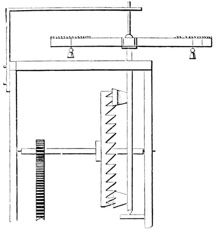
Fig. 85.—Ancient Clock Escapement.
If we have a falling weight as a time-measurer we must also have some opposing force—a regulator in fact, so that the weight becomes the source of power, and the regulator the time-measurer; therefore, in addition to the fall of the weight, we find in the earliest clocks a regulating power to prevent the weight falling too fast. So we have the two contending powers, first the weight causing the motion and then the regulator.
The first thing which was introduced as a regulator was a fly-wheel. There was a fly-wheel of a certain weight, and the force which was applied to the clock had to turn the wheel against the resistance of the air; but that did not answer well, and the first tolerable arrangement was suggested by Henry de Wyck, who constructed 178a bell and a clock in 1364, in which the fall of the weight was prevented by an oscillating balance, similar to that shown in Fig. 85.
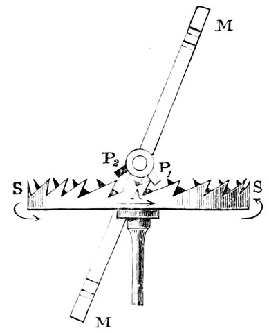
Fig. 86.—The Crown Wheel.
Here we see what is called the crown wheel (S S, shown in plan, Fig. 86), on which the escapement depends, and into the teeth of which work two pallets, P1 P2, which are placed on a vertical axis pivoted above and below. Now if we suppose a weight attached to the cord passing over a drum, so as to propel the intermediate wheels and pull them round, the crown wheel tends to rotate, but is prevented from moving until the pallets give way. Let us see how the clock goes. When the bottom tooth, presses against the pallet P1, in order to make it get out of the way and enable the wheel to go on, it twists the rod and moves the horizontal bar M M, on which are several saw-like teeth, on the intervals of which, as in the modern steelyard, weights are placed, so that the wheel pushes away the pallet and makes the horizontal beam describe a part of a circle. And what happens is this:—the upper pallet is turned out of its position and driven into 179the upper teeth of the wheel, and driven out by the further revolution of the wheel, so that the fall of the weight depends on the oscillations of the horizontal beam which carries the weights. The clock was regulated by the distance of the weights from the pivots on which the balance swung. Such was the form of clock used by Tycho Brahe, but with little success, for it was extremely irregular in its action, and Tycho still had to compare the position of one star with another instead of trusting to his clock.
There is no necessity to say much regarding the train of wheels between the weight or spring and the escapement. Their office is simply to create a great difference in velocity of rotation between the wheel turned by the weight or spring and the escape wheel, so that a slow motion with great force may be transformed into a quick motion with small force. The train of wheels is so arranged, by the consideration of the number of teeth in the wheels, that one wheel shall go round once an hour, and another once a minute, so that the first may carry the minute-hand and the other the second-hand. The hour-hand wheel is also geared to the minute-wheel, so that it shall turn once in twelve hours or twenty-four hours, according to the purposes for which the clock is required. Weights are usually used when space is no object, being more regular in their action than springs; but the latter are used for chronometers and watches, and other portable time-keepers.
The general arrangement of the clock train is shown in Fig. 87, where W is the weight, hung by a cord passing over the barrel B, on the axis of wheel G. The teeth of the wheel G gear into the pinion P1, which again is carried on the axis of the wheel C, and so on up the last 180wheel—the escape-wheel, which generally is cut to thirty teeth, so that it goes round once a minute and carries a second-hand. The pinion P1 is so arranged by the number of teeth between it and the escape-wheel that it goes round once an hour or to sixty turns of the escape-wheel.
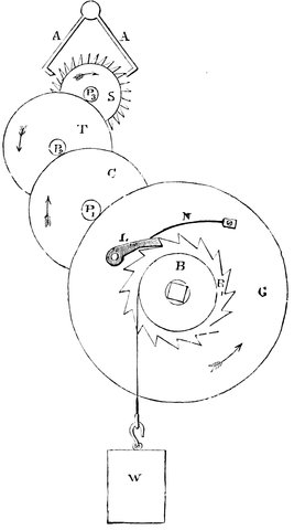
Fig. 87.—The Clock Train.
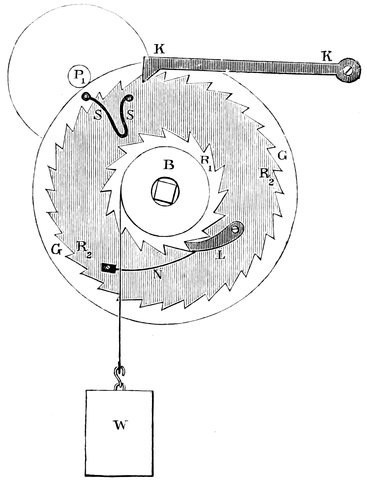
Fig. 88.—Winding Arrangements.
To wind up the clock the barrel B, Fig. 88, is turned round by the key on the square; the pawl L fastened to the wheel G allows the barrel to be turned in one direction without turning the wheel. It is obvious, however that directly we begin to wind up, the pressure on the pawl tending to turn the wheel G is removed, and the clock stops—a very objectionable thing in astronomical and other clocks supposed to keep good time. The following is one of the devices for keeping the clock going during winding,—in this case everything is the same as before, with the exception of an additional rachet-wheel R2, Fig. 88, carrying the pawl L; this wheel is loose on the axis but attached to the wheel G through the spring S. The weight therefore acts on the pawl L, and tends to drive the wheel R2, which again presses 182round the wheel G by means of the spring S, and, as the whole moves round, the teeth of the wheel R2 pass the pawl K K fixed to some part of the clock-frame. When now we commence to wind, the pressure on the pawl L and wheel R2 is removed, and the spring S S, which is always kept bent by the action of the weight, endeavours to open; and since the wheel R2 is prevented from going backwards by the pawl K, the wheel G is continually urged onwards by the spring, and the clock kept going for the short period of winding.
The clock, as left by Henry de Wyck, was only an exceedingly irregular time-keeper, and some mechanical contrivance that should beat or mark correct intervals of time was urgently required. The contrivance for beating correct intervals of time—the pendulum—was thought of by Galileo, who showed that its oscillations were isochronous, although their lengths might vary within small limits. The pendulum then was just the very thing required, and Huyghens, in 1658, applied it to clocks.
In the next form of clock, therefore, we find the pendulum introduced as a regulator. There was a crown wheel like the one in the balance clock, only instead of being vertical it was horizontal. This wheel was allowed to go round and the weight was allowed to fall by means of alternating pallets; it was in fact like that shown in Fig. 86, with the balance weights and the rod carrying them removed, and instead thereof there was a rod, attached at right angles to the end of that carrying the pallets, and hanging downwards, which, by means of a fork at its lower end, swung a pendulum to an extent equal to the go of the balance first used. Thus the pendulum was adapted by Huyghens. We have here something extremely different from the rough arrangement in which the weight was controlled by the horizontal oscillating bar carrying the weights, for the balance would go faster or slower as the crown wheel pressed harder or 184softer against the pallets, and so, if the weight acted at all irregularly the clock would go badly. But with the pendulum the control of the weight over it is small, for the bob can be made of considerable weight, because it swings from its suspending spring without friction, and such a heavy weight at the end of a long rod is scarcely altered in its rate by variations of pressure on the pallets.
Galileo and Huyghens who followed him found that the oscillations of a simple pendulum are isochronous at all places where the force of gravity is equal, and that the time of oscillation depends on the length of the pendulum—the shorter the pendulum the shorter time of oscillation, and vice versâ. The time of oscillation varying as the square root of the length.
In 1658, then, the pendulum was applied to clocks, as the balance had been before that time. But Huyghens was not slow to perceive that the circular arc of a rigid pendulum would not be sufficiently accurate for an astronomical time-keeper, when used with a clock like that employed by Tycho Brahe and the Landgrave of Hesse for their astronomical observations. Huyghens next showed that with a clock of that kind, requiring a large swing of pendulum, the oscillations were not quite isochronous, but varied in time according as the arc increased or diminished. It was clear therefore that this simple form of pendulum would not do well for the large and varying arc required to be described, but that the theoretical requirements would be satisfied if the pendulum, instead of being suspended from a rigid rod, were suspended by a cord or spring or some elastic substance which would mould itself against two curved pieces of metal, C C, Fig. 89, attached one on either side 185of the suspending spring. In swinging, the spring would wrap, as it were, gradually round either curved surface, and so virtually alter the point of suspension, and with it, of course, the virtual length of the pendulum; so that the extreme point of the pendulum U, instead of describing a circular arc K B as before, would, by means of the portions of metal at the top, have a cycloidal motion D L, the pendulum becoming virtually shorter as the spring wrapped round the pieces of metal, so that it becomes isochronous for any length of swing. But it was very soon found that the theoretically perfect clock did not after all go as well as the clock it was to replace. And it would now be difficult to say what would have happened if a few years afterwards clocks had not been made much more simple and perfect by the introduction of an entirely new escapement which permitted a very small swing.
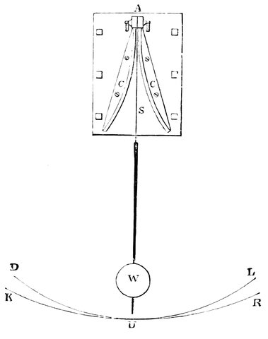
Fig. 89.—The Cycloidal Pendulum.
186If we wish a clock to go perfectly well, we have only to consider a very few things—First, the weight should be as small as possible; secondly, within reason, the pendulum should be as solidly suspended and as heavy as possible; and, thirdly, the less connection there is between the pendulum which controls the clock, and the weight which drives the clock, the better.
The latter point is provided for in the dead beat arrangement of Graham, and in the “gravity” and other forms of escapement, about which more presently. At present we have been dealing with pendulums as if they were simple pendulums, which are almost mathematical abstractions.
Everything that we have said assumes that there is a mass depending from such a fine line that the mass of the line shall not be considered; but if we examine the pendulum of some clocks we see that the rod is of steel, and that its weight or bob is elongated, and consists of a long cylinder of glass filled with mercury, and carried in a sort of stirrup of steel; this is very different from our simple pendulum—it is a compound pendulum. In a compound pendulum we have first of all the axis of suspension, which is the axis where the pendulum is supported on the top, and below that, near the centre of gravity of the pendulum, we have what is called the centre of oscillation. It will at once be perceived that as the rate of the pendulum depends upon its length, the particles in the upper part of the pendulum will be trying to go more rapidly than they can go, seeing that they are connected in one series of particles, and that the particles at the lowest portion are carried with 187greater velocity than they would be if they were left to themselves, because they are connected rigidly with the upper ones. Therefore we have to find a point, which oscillates at the same rate as it would if all the other particles were absent.
This is called the centre of oscillation, and it is on the distance of this from the point of suspension that the rate depends.
What is the use of the mercury? It is to compensate for the expansion of the rod by temperature. We shall at once see the reason of this from the fact that the pendulum gets longer by being heated, and the rate of the pendulum depends on the square root of its length; that is, if we multiply the length by four, the square root of which is two, we shall only multiply the rate by two, or double the time of oscillation. Therefore, since temperature causes all metals to vary in length, and metals are the most useful things we can employ for the support of the weights, we find that we have to consider further the alteration of the length of the pendulum due to the variation of the length of the metal we employ. Hence, in addition to the necessity of an arrangement which gives the shortest possible swing, we require also a method for compensating for changes of temperature.
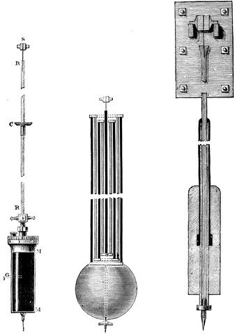
Fig. 90.—Graham’s, Harrison’s, and Greenwich Pendulums.
We have not space to go through the history of compensating pendulums, but we may direct attention to some of the best results which have been obtained in this matter. We will first examine the mercurial pendulum, Fig. 90, which we have referred to. In this case the compensation is accomplished as follows: Mercury is inclosed in a glass cylinder M M; shown in the left hand side of the figure; and as the mercury expands more than the glass, it will rise to a higher level on being heated; and the lengthening of the steel rod R R will be counteracted by a similar 189lengthening due to the expansion of mercury, so that the centre of oscillation is carried down by the steel rod, and up by the mercury, and it is therefore not displaced if the proper ratio is maintained between the length of the steel rod and the column of mercury in the glass vessel. The mercury in the glass will lengthen fifteen times as much as the steel rod, if we have equal lengths of each, so that in order that they may expand equally the rod must be fifteen times as long as the mercury column. This would keep the top of the mercury at the same distance from the point of suspension, but we want to keep the centre of oscillation, which is about half way down the column, at the same distance, so we double the height of the mercury, making it two-fifteenths of the length of the steel rod, so that the surface is over-compensated, but the centre of oscillation is exactly corrected. An astronomer can alter the amount of mercury as he pleases, making it now more, now less, till the stars tell him he has done the right thing, and the pendulum is compensated, and the clock keeps correct time at all temperatures.
The little sliding cup C is to carry small weights for final delicate adjustment, the addition of a weight thus obviously tending to increase the rate of the pendulum.
This is Graham’s mercurial pendulum, invented by him in 1715. There is another compensating pendulum, called Harrison’s gridiron pendulum, from the bars of metal sustaining the pendulum being arranged gridiron fashion, Fig. 90. At the top is a knife edge or spring for the centre of suspension, and the pendulum bob is suspended by a system of rods, the five black ones being made of a less expansible metal than the other four; consequently, as the five black ones expand and tend to 190lower the bob, the intermediate ones expand also and tend to raise it; the length of the black rods exceeding that of the others, these latter must be made of a more expansible metal to make up for their smaller length. Thus the acting length of the shaded rods is two-thirds of the acting length of the black ones (each pair is considered as one rod because they act as such), so that a metal is used for the former which expands more than that used for the latter in the proportion of about three to two, and brass is found to answer for the most expansible metal, and steel for the less. These rods are packed side by side, and look very ornamental. If l be the length of the brass rods, and l´ that of the steel rods, and e the coefficient of expansion of the brass, and e´ that of the steel, then l: l´:: e´: e. The pendulum is then compensated, and the bob remains at the same distance from the centre of suspension at all temperatures.
For the pendulum of the clock at the Royal Observatory a modification of the gridiron form has been adopted; for it was found on trial with a mercurial pendulum that the steel rod gained in temperature more rapidly than the mercury, and lost heat quicker, so that the pendulum did not compensate immediately on a change of temperature. The form adopted is as follows (Fig. 90):—A steel rod is suspended as usual, and is encircled by a zinc tube resting on the nut for rating the pendulum; the zinc tube is again encircled by a steel tube resting on the top of the zinc tube and carrying at its lower end a cylindrical leaden bob attached at its centre to the steel tube; slots and holes are cut in the tubes to expose the inner parts to the air, so that each will experience the change of temperature at the same 191time. It is of course possible that the tubes forming the pendulum rod are not of exactly the right length to perfectly compensate; a final delicate adjustment is therefore added. On the crutch axis, and held by a collar to it, are two compound bars of brass and steel, h and i, Fig. 96. The collar fits loosely on the axis, so that the rods, which carry small weights at their extremities, can be easily shifted to make any angle with the horizontal; then, since brass expands more than steel for the same degree of heat, the bars will bend on being heated or cooled, and if the brass be uppermost the weights at the ends of the rods will be lowered with an increase of temperature, and will tend to increase the rate of the pendulum, and vice versâ. So long as the rods are horizontal and in the same straight line their centre of gravity is in the crutch axis, and they are therefore balanced in every position; they therefore only retard the pendulum by their inertia; but when the ends are bent down the centre of gravity is lowered, and they have a tendency to come to a horizontal position and to balance each other like a scale beam, and so swing with the pendulum and overcome its retardation.
It is obvious that they would, if alone, swing in a shorter time than the pendulum and so, being connected, they increase its rate.
When the rods are vertical they have no compensating action, for the centre of gravity is simply thrown sidewise, and acts as a continuous force tending to make the pendulum oscillate further on one side than on the other; and in the intermediate positions of the rods their action varies, and a consideration of the position of their centre of gravity will give the intensity of the compensating action. In order to make a small change in the rate of 192the clock without stopping it to turn the screw at the bottom of the pendulum, the following contrivance is adopted.
A weight k slides freely on the crutch rod, but is tapped to receive the screw cut on the lower portion of the spindle l, the upper end of which terminates in a nut m at the crutch axis. By turning this nut the position of the small weight on the crutch rod is altered, and the clock rate correspondingly changed. To make the clock lose, the weight must be raised.
There is also another method of compensation, depending on differential expansion. Attached to an ordinary pendulum just above the bob, and at right angles to it, is a composite rod, made of copper and iron, the lower half being copper; then, as the pendulum rod lengthens and lets down the bob, the copper expands more than the iron, and causes the rod to bend, like a piece of wood wetted on one side, and by this bending or warping the weights at either end are raised as the bob is lowered, so the centre of oscillation keeps at the same height at all temperatures.
We have dealt with clocks and pendulums somewhat in the order of their invention. We may add that the great majority of clocks of modern manufacture of any pretention to time-keepers are constructed with the dead beat escapement of Graham or a modification of it, combined with a mercurial or gridiron pendulum. For the best Observatory clocks of the more expensive kind other more elaborate forms of escapement are sometimes used, as, for example, that in the clock at the Royal Observatory, Greenwich, which we shall refer to in detail further on, on account of other new points in its construction.
193Now, having a clock good enough to use with the transit instrument, it is necessary to take the utmost precautions with reference to it. The Russian astronomers have inclosed their clock in a stone case, and placed it many yards below the ground, endeavouring thus to get rid of the action of temperature, which changes the length of the steel pendulum rod. But that is not all; after we have corrected our clock as well as we can from the point of view of temperature, it is still found that there may be a variation, amounting to something considerable, due to another cause. If the barometer changes an inch or an inch and a half by change of pressure of the air, the rate of the pendulum will alter, and the cause of the variation it is impossible to prevent without putting the clock in a vacuum, so that changes of the barometer must be allowed for.
There are, however, methods of compensating the pendulum for changes of pressure if desirable: one way of doing this is to pass the suspending spring of the pendulum through a slit in a metal plate, which then becomes virtually the point of suspension; this plate is then raised or lowered by an aneroid barometer, or by a float in an ordinary cistern barometer so that the length of the pendulum is virtually altered with the pressure of the atmosphere. At Greenwich the Astronomer-Royal has adopted the following expedient: A magnet at the lower end of the pendulum passes at each swing near a magnet which is raised or lowered by means of a float in the cistern of a barometer. The magnet then has a greater or less influence on the pendulum magnet according as the pressure of the air varies, and so adds a variable amount to the effect of gravity and therefore to the rate of oscillation.
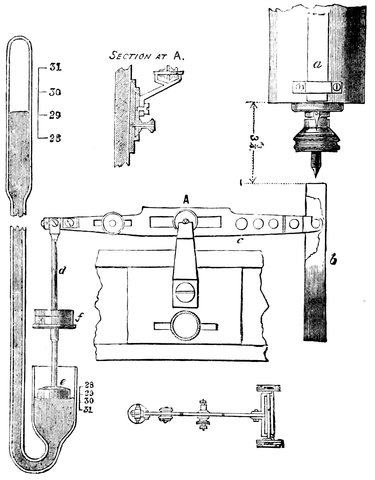
Fig. 91.—Greenwich Clock: arrangement for Compensation for Barometric Pressure.
This principle is carried out as follows:—Two bar
magnets, each about six inches long, are fixed vertically
to the bob of the clock pendulum; one in front, a, Fig.
91, the other at the back. The lower pole of the front
magnet is a north pole; the lower pole of the back
magnet is a south pole. Below these a horse-shoe magnet,
b, having its poles precisely under those of the pendulum
magnets, is carried transversely at the end of the lever c,
the extremity of the opposite arm of the lever being
attached by the rod d, to the float e in the lower leg of
195a syphon barometer. The lever turns on knife edges.
A plan of the lever (on a smaller scale) is given, as well
as a section through the point A. Weights can be
added at f to counterpoise the horse-shoe magnet. The
rise or fall of the mercurial barometer correspondingly
raises or depresses the horse shoe magnet, and, increasing
or decreasing the magnetic action between its poles and
those of the pendulum magnets, compensates, by the
change of rate produced, for that arising from variation
in the pressure of the atmosphere. The shorter leg of
the barometer in which the float rests has an area of
four times that of the barometer tube at the upper
surface of the mercury, so that for a large change of
barometric height the magnet is only moved a small
distance, a change of one inch of the barometer lowering
the surface in the short leg 2
10 inch; the distance between
the pendulum magnets and the horse-shoe magnets is
3¾ inches.
The invention of the pendulum, its application, and the improvements thereon having been described, it remains to treat of the equally important improvements on the escapement. The first change for the better appears to have been due to Hooke, who in 1666 brought before the Royal Society the crutch, or anchor escapement, whereby the arc through which the pendulum vibrated was so much reduced that Huyghens’s cycloidal curves became unnecessary, and the power required to drive the clock was materially reduced.
This escapement, common in ordinary eight-day clocks, is different from that previously described in the way in which the crown wheel or escape wheel is regulated.
We have come back to a vertical escape wheel as it was in the clock used by Tycho; but instead of using two pallets on a rod which regulated the wheel, we have here an anchor escapement (Fig. 92) in connection with the pendulum; and what happens is this—when the pendulum is made to oscillate, these pallets P P gradually move in and out of the teeth of the wheel, and let a tooth pass at every swing; and it is obvious that when the wheel and anchor are nicely adjusted, an extremely small motion of the anchor, and consequently a small oscillation of the pendulum, allows the escape wheel to turn round, and the clock to go.
The greater regularity of this form of escapement is due to a smaller oscillation of the pendulum being required than with the form first described; for it is 197found that the motion of a pendulum when vibrating through not more than six degrees is practically cycloidal, and it is only with larger arcs that the circle materially differs from the theoretical curve required.
The pendulum is kept in vibration by the escape wheel, or rather by its teeth pressing against the inclined surfaces of the pallets, and forcing them outwards, and so giving the pendulum an impulse prior to each tick.
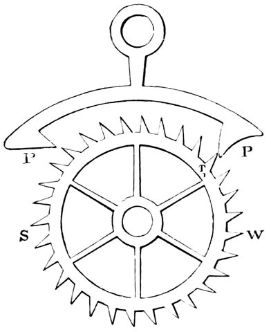
Fig. 92.—The Anchor Escapement.
This anchor escapement, which was invented by “Clement, of London, clockmaker,” forms, as it were, the basis of our modern clocks, and, with the exception of the dead beat, which was due to Graham some years afterwards, is in almost exclusive use at the present date.
We see that as soon as a tooth has escaped on one side, a tooth on the other begins immediately to retard the action of the pendulum by pressing against the inclined surface of the other pallet, and as the pendulum swings on, the tooth gives way, and the motion of the wheel is reversed; then when the pendulum begins to return, 198it is assisted again by the tooth, so that the pendulum is always under the influence of the escape wheel, some times accelerated, and sometimes retarded. The principle of Graham’s dead beat is to get rid of the retarding action of the escape wheel, so that there should be no necessity for so much accelerating power, and the pendulum should be out of the influence of the escape wheel during a large portion of its vibration. This he accomplished by doing away with a large portion of the inclined surface of the pallet (Fig. 93), so that the teeth have no accelerating action on the pendulum until just as they leave the ends of the pallets where they are inclined; the greater portion of both the pallets on which the escape wheel works being at right angles to its direction of motion, the teeth have no tendency to force the pallet outwards. In Fig. 93 the tooth V has fallen on the pallet D, the tooth T having just been released, and as the pendulum still swings on in the direction of the arrow, the pallet D will be pushed further under the tooth C but without pressing the wheel backwards, and without retardation other than that of friction. When the pendulum returns and the pallet just gets past the position shown, it gets an impulse, and this is given as nearly as possible as much before the pendulum reaches its vertical position as after it passes it, its action is therefore neither to increase nor diminish the rate. In this escapement not only is the arc of oscillation considerably lessened and the motion of the pendulum brought near to the cycloidal form, but in addition to this there is this important point, that the weight is acting upon the pendulum for the least possible time.
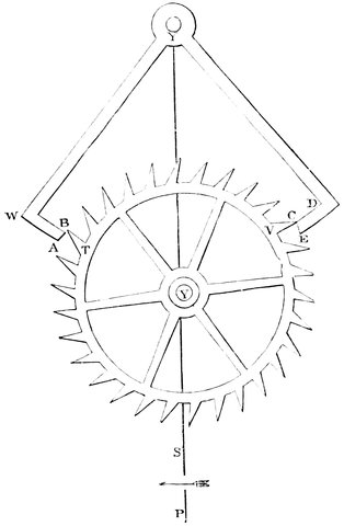
Fig. 93.—Graham’s Dead Beat.
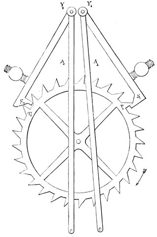
Fig. 94.—Gravity Escapement (Mudge).
We will now describe the more elaborate forms of escapement, and we will take first the gravity escapement, as it is called. The principle of its action consists in there being a small impulse given to the pendulum at each oscillation, by means of two small rods hanging, one on each side of it, and tending by their own weight to force the pendulum into a vertical position; these rods are alternately pushed outwards by the escapement before the pendulum in its swing arrives at them, and then they are allowed to press against it on its return towards the vertical, so that the pendulum has a constant force acting on it at each oscillation, unconnected with the clock movement. This is carried out in the escapement invented by Mudge, as shown in Fig. 94. The pendulum rod is supposed to be hanging just in front of the rods hanging from the pivots Y1 Y2, and on swinging it presses against the pins at the lower ends of the rods and so lifts the pallets S1 S2 out of the teeth of the escape wheel. In the position shown the pendulum is 201moving to the right, having been gently urged from the left by the weight of the pallet rod Y2 S2, and the pallet S1 has been lifted outwards by the tooth acting on its inclined surface. On the pendulum rod reaching the pin the rod is moved outwards and the end of the pallet S1 pushed out of the tooth when the wheel moves on, at the same time pushing outwards the pallet S2. As the pendulum returns towards the left again the rod Y1 follows it, giving it a gentle impulse by its own weight until it returns nearly to the vertical or to the corresponding position in which Y2 S2 is shown. On the pendulum swinging on and releasing T2 the pallet S1 is again pushed outwards by the inclined plane to the position shown in the diagram. In this escapement there was danger of the pallets being thrown too violently outwards so that the teeth were not caught by the flat surfaces at the ends, and Mr. Bloxam improved on it by letting the pallets be thrown outwards by a small wheel on the axis of the escape wheel so that the action was less rapid; he accomplished this in the following manner. On the end of the axis of the last wheel are a number of arms A A, Fig. 95, say nine, about 1½ inches long, which are prevented from revolving by studs L1 L2 on the inside of each hanging rod P1 P2; then, as each rod is pushed outwards by the pendulum, an arm escapes from a stud and the clock goes on one second. Each rod is pushed outwards by the clock almost sufficiently far for the arm to escape, but not quite, so that the pendulum just releases the arm at the end of its swing in the same manner as in Mudge’s escapement, Fig. 94; but instead of the teeth of the escape wheel pushing the rods outwards there is the small wheel T1 T2, having the same number of teeth as there are arms on the axis and close to them, and the 202projecting pieces H1 H2 at right angles to each swinging rod rest against the teeth of this wheel, one resting against the teeth at the top and the other at the bottom, so that they catch against the teeth after the manner of a ratchet, and the rods are pushed outwards by this wheel as it revolves. The arms and ratchet wheel are so set that, during the motion of an arm A, to a stud, a tooth of the ratchet wheel is pushing outwards the rod carrying that stud. The action is as follows:—The pendulum having just swung up to a rod and released the arm pressing against its stud, the arms and ratchet wheel revolve, and the tooth of the ratchet wheel, which had been pressing outwards the swinging rod, passes on free of the projecting piece, which can now move backwards to the next tooth; so the rod, being no longer supported, presses against the pendulum rod on its return oscillation. The arms and ratchet wheel revolve until an arm on the opposite side comes in contact with the stud on the other rod, and in revolving the ratchet wheel throws outwards this rod just so far that the arm is not released. The pendulum is assisted by the weight of the first rod to the vertical position, when the projecting piece of the rod comes in contact with the next tooth of the ratchet wheel where it rests until the oscillation is completed, and the second arm is released. It is then forced outwards, and the next arm on that side presses against the stud, when a repetition of the foregoing takes place. In this way the clock is kept going without any direct action of the clock train on the pendulum.
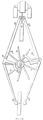
Fig. 95.—Gravity Escapement (Bloxam).
203Another very beautiful escapement is that devised by the Astronomer-Royal and carried out in the clock erected in 1871 at Greenwich.[9] In this case the pendulum is free except during a portion of every alternate second, when it releases the escapement and receives 204an impulse, so that there is a tick only at every other second.
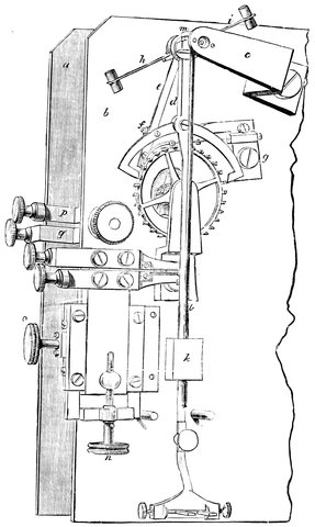
Fig. 96.—Greenwich Clock Escapement.
The details of the escapement may be seen in Fig. 96, which gives a general view of a portion of the back 205plate of the clock movement, supposing the pendulum removed; a and b are the front and back plates respectively of the clock train; c is a cock supporting one end of the crutch axis; d is the crutch rod carrying the pallets, and e an arm carried by the crutch axis and fixed at f to the left-hand pallet arm; g is a cock supporting a detent projecting towards the left and curved at its extreme end; at a point near the top of the escape wheel this detent carries a pin (jewel) for locking the wheel, and at its extreme end there is a very light “passing spring.” The action of the escapement is as follows:—Suppose the pendulum to be swinging from the right hand. It swings quite freely until a pin at the end of the arm e lifts the detent; the wheel escapes from the jewel before mentioned, and the tooth next above the left-hand pallet drops on the face of the pallet (the state shown in the figure), and gives impulse to the pendulum; the wheel is immediately locked again by the jewel, and the pendulum, now detached, passes on to the left; in returning to the right, the light passing spring, before spoken of, allows the pendulum to pass without disturbing the detent; on going again to the left, the pendulum again receives impulse as already described. The right-hand pallet forms no essential part of the escapement, but is simply a safety pallet, designed to catch the wheel in case of accident to the locking-stone during the time that the left-hand pallet is beyond the range of the wheel. The escape wheel carrying the seconds hand thus moves once only in each complete or double vibration of the pendulum, or every two seconds.
We have now given a description of the astronomical clock—the modern astronomical instrument which it was our duty to consider. There is another time-keeper—the chronometer—which we have to dwell upon. In the chronometer, instead of using the pendulum, we have a balance, the vibration of which is governed by a spiral spring, instead of by gravity, as the pendulum is. By such means we keep almost as accurate time as we do by employing a pendulum, the balance being corrected for temperature on principles, one of which we shall describe.
We must premise by saying that fully four-fifths of the compensation required by a chronometer or watch-balance is owing to the change in elasticity of the governing spiral spring, the remainder, comparatively insignificant, being due to the balance’s own expansion or contraction. The segments R1, R2 of the balance (see Fig. 97) are composed of two metals, say copper and steel, the copper being exterior; then as the governing spiral spring loses its elasticity by heat, the segments R1, R2 curve round and take up positions nearer the axis of motion, the curvature being produced by the greater expansion of copper over steel; and thus the loss of time due to the loss of elasticity of the spiral spring is compensated for.
This balance may be adjustable by placing on the arms small weights, W W, which may be moved along the arms, and so increase or diminish the effect of temperature at pleasure.
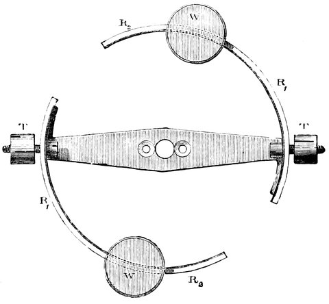
Fig. 97.—Compensating Balance.
Of the number of watch and chronometer escapements we may mention the detached lever—the one most generally used for the best watches, the form is shown in Fig. 98. P P are the pallets working on a pin at S as in the dead-beat clock escapement; the pallets carry a lever L which can vibrate between two pins B B. R is a disc carried on the same axis with the balance, and it carries a pin I, which as the disc goes round in the direction of the arrow, falls into the fork of the lever, and moves it on and withdraws the pallet from the tooth D, which at once moves onwards and gives the lever an impulse as it passes the face of the pallet. This impulse is communicated to the balance through the pin I, the balance is kept vibrating in contrary directions under the influence of the hair-spring, gaining an impulse at each swing. On the same axis as R is a second disc O with a 208notch cut in it into which a tongue on the lever enters; this acts as a safety lock, as the lever can only move while the pin I is in the fork of the lever.
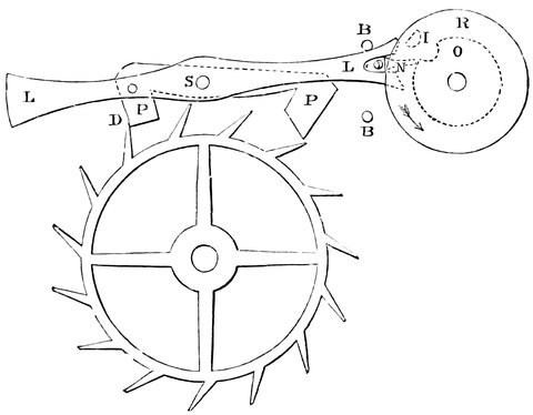
Fig. 98.—Detached Lever Escapement.
The escapement we next describe is that most generally used in chronometers. S S, Fig. 99, is the escape wheel which is kept from revolving by the detent D. On the axis of the balance are two discs, R1, R2, placed one under the other. As the balance revolves in the direction of the arrow, the pin P2 will come round and catch against the point of the detent, lifting it and releasing the escape-wheel, which will revolve, and the tooth T will hit against the stud P1, giving the balance an impulse. The balance then swings on to the end of its course and returns, and the stud P2 passes the detent as follows: a light spring Y Y is fastened to the detent, projecting a little beyond it, and it is this spring, and not the detent itself, that the pin P2 touches: on the return of P2 it simply lifts the spring away from the detent and passes it, whereas 209in advancing the spring was supported by the point of the detent, and both were lifted together.
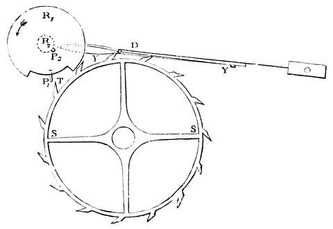
Fig. 99.—Chronometer Escapement.
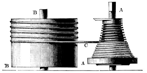
Fig. 100.—The Fusee.
In watches and chronometers and in small clocks a coiled spring is used instead of a weight, but its action is irregular, since when it is fully wound up it exercises greater force than when nearly down. In order to compensate for this the cord or chain which is wound round the barrel containing the spring passes round a conical barrel called a fusee (Fig. 100): B is the barrel containing the spring and A A the fusee. One end of the spring is 210fixed to the axis of the barrel, which is prevented from turning round, and the other end to the barrel, so that on winding up the clock by turning the fusee the cord becomes coiled on the latter, and the more the spring is wound the nearer the cord approaches the small end of the fusee, and has therefore less power over it; while as the clock goes and the spring becomes unwound, its power over the axis becomes greater. The power, therefore, acting to turn the fusee remains pretty constant.
9. By Messrs. E. Dent and Co. of the Strand.
One of the great advantages which astronomy has received from the invention of the telescope is the improved method of measuring space and determining positions by the use of the telescope in the place of pointers on the old instruments. The addition of modern appliances to the telescope to enable it to be used as an accurate pointer, has played a conspicuous part in the accurate measurement of space, and the results are of such importance, and they have increased so absolutely pari passu with the telescope, that we must now say something of the means by which they have been brought about.
For astronomy of position, in other words for the measurement of space, we want to point the telescope accurately at an object. That is to say, in the first instance we want circles, and then we want the power of not only making perfect circles, but of reading them with perfect accuracy; and where the arc is so small that the circle, however finely divided, would help us but little, we want some means of measuring small arcs in the eyepiece of the telescope itself, where the object appears to us, as it is called, in the field of view; we 212want to measure and inspect that object in the field of view of the telescope, independently of circles or anything extraneous to the field. We shall then have circles and micrometers to deal with divisions of space, and clocks and chronographs to deal with divisions of time.
We require to have in the telescope something, say two wires crossed, placed in the field of view—in the round disc of light we see in a telescope owing to the construction of the diaphragm—so as to be seen together with any object. In the chapter on eyepieces it was shown that we get at the focus the image of the object; and as that is also the focus of the eyepiece, it is obvious that not only the image in the air, as it were, but anything material we like to put in that focus, is equally visible. By the simple contrivance of inserting in this common focus two or more wires crossed and carried on a small circular frame, we can mark any part of the field, and are enabled to direct the telescope to any object.
In the Huyghenian eyepiece, Fig. 60, the cross should be between the two convex lenses, for if we have an eyepiece of this kind the focus will be at F, and so here we must have our cross wires; but, if instead of this eyepiece we have one of the kind called Ramsden’s eyepiece, Fig. 62, with the two convex surfaces placed inwards, then the focus will be outside, at F, and nearer to the object-glass: therefore we shall be able to change these eyepieces without interfering with the system of wires in the focus of the telescope. We hence see at once that the introduction of this contrivance, which is due to Mr. Gascoigne, at once enormously increases the possibility of making accurate observations by means of the telescope.
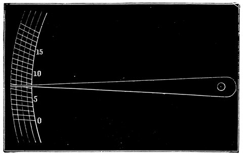
Fig. 101.—Diggs’ Diagonal Scale.
Hipparchus was content to ascertain the position of the celestial bodies to within a third of a degree, and we are informed that Tycho Brahe, by a diagonal scale, was able to bring it down to something like ten seconds. Fig. 101 will show what is meant by this. Suppose this to be part of the arc of Tycho’s circle, having on it the different divisions and degrees. Now it is clear that when the bar which carried the pointer swept over this arc, divided simply into degrees, it would require a considerable amount of skill in estimating to get very close to the truth, unless some other method were introduced; and the method suggested by Diggs, and adopted by Tycho, was to have a series of diagonal lines for the divisions of degrees; and it is clear that the height of the diagonal line measured from the edge of the circle could give, as it were, a longer base than the direct distance between each division for determining the subdivisions of the degree, and a slight motion of the pointer would make a great difference in the point where it cuts the diagonal line. For instance, it would not be easy to 214say exactly the fraction of division on the inner circle at which the pointer in Fig. 101 rests, but it is evident that the leading edge of the pointer cuts the diagonal line at three-fourths of its length, as shown by the third circle; so the reading in this case is seven and three-quarters; but that is, after all, a very rough method, although it was all the astronomer had to depend upon in some important observations.
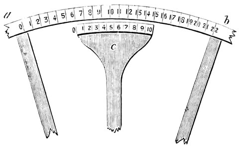
Fig. 102.—The Vernier.
The next arrangement we get is one which has held its own to the present day, and which is beautifully simple. It is due to a Frenchman named Vernier, and was invented about 1631. We may illustrate the principle in this way. Suppose for instance we want to subdivide the divisions marked on the arc of a circle, Fig. 102 a b, and say we wish to divide them into tenths, what we have to do is this—First, take a length equal to nine of these divisions on a piece of metal, c, called the vernier, carried on an arm from the centre of the circle, and then, on a separate scale altogether, divide that distance not into nine, as it is divided on the circle, but into ten portions. Now mark what happens as the vernier sweeps along the circle, instead of having Tycho’s pointer sweeping across the diagonal scale.
215Let us suppose that the vernier moves with the
telescope and the circle is fixed; then when division 0
of the vernier is opposite division 6 on the circle we
know that the telescope is pointing at 6° from zero
measured by the degrees on this scale; but suppose, for
instance, it moves along a little more, we find that line
1 of the vernier is in contact with and opposite to
another on the circle, then the reading is 6° and ⅒°;
it moves a little further, and we find that the next line
2, is opposite to another, reading 6° and 2
10°, a little
further still, and we find the next opposite. It is
clear that in this way we have a readier means of dividing
all those spaces into tenths, because if the length
of the vernier is nine circle divisions the length of each
division on the vernier must be as nine is to ten, so
that each division is one-tenth less than that on
the circle.
We must therefore move the vernier one-tenth of a
circle division, in order to make the next line correspond.
That is to say, when the division of the vernier marked
0 is opposite to any line, as in the diagram, the reading
is an exact number of degrees; and when the division 1
is opposite, we have then the number of degrees given by
the division 0 plus one-tenth; when 2 is in contact,
plus two-tenths; when 3 is in contact, plus three-tenths;
when 4 is in contact, plus four-tenths, and so on, till we
get a perfect contact all through by the 0 of the vernier
coming to the next division on the circle, and then we
get the next degree. It is obvious that we may take
any other fraction than to for the vernier to read to, say
1
60, then we take a length of 59 circle divisions on the
vernier and divide it into 60, so that each vernier
division is less than a circle division by 1
60. This is a
216method which holds its own on most instruments, and is
a most useful arrangement.
But most of us know that the division of the vernier has been objected to as coarse and imperfect; and Sharp, Graham, Bird, Ramsden, Troughton, and others found that it is easy to graduate a circle of four or five feet in diameter, or more, so accurately and minutely that five minutes of arc shall be absolutely represented on every part of the circle. We can take a small microscope and place in its field of view two cross wires, something like those we have already mentioned, so as to be seen together with the divisions on the circle, and then, by means of a screw with a divided head, we can move the cross wires from division to division, and so, by noting the number of turns of the screw required to bring the cross wires from a certain fixed position, corresponding to the pointer in the older instruments, to the nearest division, we can measure the distance of that division from the fixed point or pointer, as it were, just as well as if the circle itself were much more closely divided. We can have matters so arranged that we may have to make, if we like, ten turns of the screw in order to move the cross wires from one graduation to the next, and we may have the milled head of the screw itself divided into 100 divisions, so that we shall be able to divide each of the ten turns into 100, or the whole division into 1,000 parts. It is then simply a question of dividing a portion of arc equal to five minutes into a thousand, or, if one likes, ten thousand parts by a delicate screw motion.
We are now speaking of instruments of precision, in which large telescopes are not so necessary as large circles. With reference to instruments for physical and 217other observations, large circles are not so necessary as large telescopes, as absolute positions can be determined by instruments of precision, and small arcs can, as we shall see in the next chapter, be determined by a micrometer in the eyepiece of the telescope.
It will have been gathered from the previous chapter that the perfect circles nowadays turned out by our best opticians, and armed in different parts by powerful reading microscopes, in conjunction with a cross wire in the field of view of the telescope to determine the exact axis of collimation, enable large arcs to be measured with an accuracy comparable to that with which an astronomical clock enables us to measure an interval of time.
We have next to see by what method small arcs are measured in the field of view of the telescope itself. This is accomplished by what are termed micrometers, which are of various forms. Thus we have the wire micrometer, the heliometer, the double-image micrometer, and so on. These we shall now consider in succession, entering into further details of their use, and the arrangements they necessitate when we come to consider the instrument in conjunction with which they are generally employed.
The history of the micrometer is a very curious one. We have already spoken of a pair of cross wires replacing the pinnules of the old astronomers in the field of view of the telescope, so that it might be pointed to any 219celestial object very much more accurately than it could be without such cross wires. This kind of micrometer was first applied to a telescope by Gascoigne in 1639. In a letter to Crabtree he writes:[10] “If here (in the focus of the telescope) you place the scale that measures ... or if here a hair be set that it appear perfectly through the glass ... you may use it in a quadrant for the finding of the altitude of the least star visible by the perspective wherein it is. If the night be so dark that the hair or the pointers of the scale be not to be seen, I place a candle in a lanthorn, so as to cast light sufficient into the glass, which I find very helpful when the moon appeareth not, or it is not otherwise light enough.”
This then was the first “telescopic sight,” as these arrangements at the common focus of the object-glass and eyepiece were at first called. It is certain that we may date the micrometer from the middle of the seventeenth century; but it is rather difficult to say who it was who invented it. It is frequently attributed to a Frenchman named Auzout, who is stated to have invented it in 1666; but we have reason to know that Gascoigne had invented an instrument for measuring small distances several years before. Though first employed by Gascoigne, however, they were certainly independently introduced on the Continent, and took various forms, one of them being a reticule, or network of small silver threads, suggested by the Marquis Malvasia, the arc interval of which was determined by the aid of a clock. Huyghens had before this proposed, as specially applicable to the measures of the diameters of planets and the like, the introduction of a tapering slip of metal. The part of the slip which exactly eclipsed 220the planet was noted; it was next measured by a pair of compasses, and having the focal length of the telescope, the apparent diameter was ascertained.
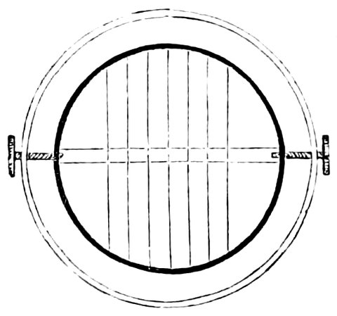
Fig. 103.—System of Wires in a Transit Eyepiece.
Malvasia’s suggestion was soon seized upon for determinations of position. Römer introduced into the first transit instrument a horizontal and a number of vertical wires. The interval between the three he generally used was thirty-four seconds in the equator, and the time was noted to half seconds. The field was illuminated by means of a polished ring placed outside of the object-glass. The simple system of cross wires, then, though it has done its work, is not to be found in the telescope now, either to mark the axis of collimation, or roughly to measure small distances. For the first purpose a much more elaborate system than that introduced by Römer is used. We have a large number of vertical wires, the principal object of which is, in such telescopes as the transit, to determine the absolute time of the passage of either a star or planet, or the sun or moon, over the meridian; and one or more horizontal ones. These constitute the modern transit eyepiece, a very simple form of which is shown in the above woodcut.
The wire micrometer is due to suggestions made independently by Hooke and Auzout, who pointed out how valuable the reticule of Malvasia would be if one of the wires were movable.

Fig. 104.—Wire Micrometer. x and y are thicker wires for measuring positions on a separate plate to be laid over the fine wires.
The first micrometer in which motion was provided consisted of two plates of tin placed in the eyepiece, being so arranged and connected by screws that the distances between the two edges of the tin plates could be determined with considerable accuracy. A planet could then be, as it were, grasped between the two plates, and its diameter measured; it is very obvious that what would do as well as these plates of tin would be two wires or hairs representing the edges of these tin plates; and this soon after was carried out by Hooke, who left his mark in a very decided way on very many astronomical arrangements of that time. He suggested that all that was necessary to determine the diameter of Saturn’s rings was to have a fixed wire in the eyepiece, and a second wire travelling in the field of view, so that the planet or the ring could be grasped between those two wires.
The wire-micrometer. Fig. 104, differs little from the 222one Hooke and Auzout suggested, A A is the frame, which carries two slides, C and D, across the ends of each of which fine wires, E and B, are stretched; then, by means of screws, F and G, threaded through these movable slides and passing through the frame A A, the wires can be moved near to, or away from, each other. Care must be taken that the threads of the screw are accurate from one end to the other, so that one turn of the screw when in one position would move the wire the same distance as a turn when in another position. In this micrometer both wires are movable, so as to get a wide separation if needful, but in practice only one is so, the other remaining a fixture in the middle of the field of view. There is a large head to the screw, which is called the micrometer screw, marked into divisions, so that the motion of the wire due to each turn of the screw may be divided, say into 100 parts, by actual division against a fixed pointer, and further into 1,000 parts by estimation of the parts of each division. Hooke suggested that, if we had a screw with 100 turns to an inch, and could divide these into 1,000 parts, we should obviously get the means of dividing an inch into 100,000 parts; and so, if we had a screw which would give 100 turns from one side of the field of view of the telescope to the other, we should have an opportunity of dividing the field of view of any telescope into something like 100,000 parts in any direction we chose.
The thick wires, x, y, are fixed to the plate in front of, but almost touching, the fine wires, and in measuring, for instance, the distance of two stars the whole instrument is turned round until these wires are parallel to the direction of the imaginary line joining them.
223This was the way in which Huyghens made many important measures of the diameters of different objects and the distances of different stars. Thus far we are enabled to find the number of divisions on the micrometer screw that corresponds to the distance from one star to another, or across a planet, but we want to know the number of seconds of arc in the distance measured.
In order to do this accurately we must determine how
many divisions of the screw correspond to the distance
of the wires when on two stars, say, one second apart.
Here we must take advantage of the rate at which a star
travels across the field when the telescope is fixed, and we
separate the wires by a number of turns of the screw, say
twenty, and find what angle this corresponds to, by letting
a star on or near the equator[11] traverse the field, and
noticing the time it requires to pass from one wire to
the next. Suppose it takes 26⅔ seconds, then, as fifteen
seconds of arc pass over in one second of time, we must
multiply 26 by 15, which gives 400, so that the distance
from wire to wire is 400 seconds of arc; but this
is due to twenty revolutions of the screw, so that
each revolution corresponds to 400
20˝, or twenty seconds,
and as each revolution is divided into 100 parts,
and 20
100˝ = ⅕˝ therefore each division corresponds
to ⅕˝ of arc.
We shall return to the use of this most important instrument when we have described the equatorial, of which it is the constant companion.
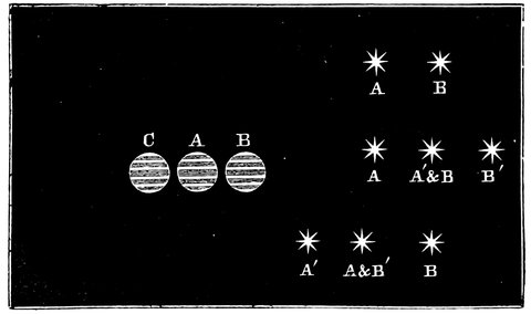
Fig. 105.—A B C. Images of Jupiter supposed to be touching; B being produced by duplication, C duplicate image on the other side of A.
A B, Double Star; A, A´ & B, B´, the appearance when duplicate image is moved to the right; A´, A & B´, B, the same when moved to the left.
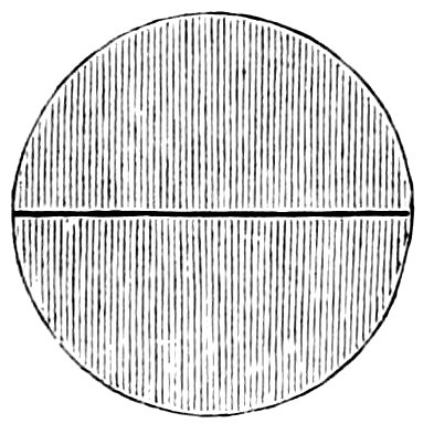
Fig. 106.—Object-glass cut into two parts.
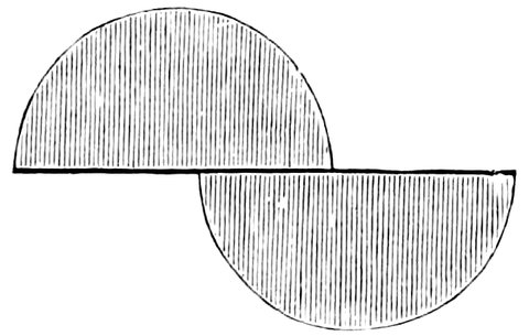
Fig. 107.—The parts separated, and giving two images of any object.
There are other kinds of micrometers which we must also briefly consider. In the heliometer[12] we get the power of measuring distances by doubling the images of the objects we see, by means of dividing the object-glass. The two circles, A and B, Fig. 105, represent the two images of Jupiter formed, as we shall show presently, and touching each other; now, if by any means we can make B travel over A till it has the position C, also just touching A, it will manifestly have travelled over a distance equal to the diameters of A and B, so that if we can measure the distance traversed and divide it by 2, we shall get the diameter of the circle A, or the planet. The same principle applies to double stars, for if we double the stars A and B, Fig. 105, so that the secondary images become A´ and B´, we can move A´ over B, and then only three stars will be visible; we can then move the secondary images back over A and B till B´ comes over A, and the second image of A comes to A´. It is thus manifest that the images A´ and B´ on being moved to A´ and B´ in the second position have passed over double their distance apart. Now all double-image micrometers depend on this principle, and first we will explain how this duplication of images is made in the heliometer. It is clear that we shall not alter the power of an object-glass to bring objects to focus if we cut the object-glass in two, for if we put any dark line across the object-glass, which optically cuts it in two, we shall get an image, say of Jupiter, unaltered. But suppose instead of having the parts of the object-glass in their original position after we have cut the object-glass in two, we make one half of the object-glass travel over the other in the manner represented in Fig. 107. Each of these halves of the object-glass will be competent to give us a different image, and the light forming each image will be half the light we got from the two halves of the object-glass combined; but when one half is moved we shall get two images in two different places in the field of view. We can so alter the position of the images of 226objects by sliding one half of the object-glass over the other, that we shall, as in the case of the planet Jupiter, get the two images exactly to touch each other, as is represented in Fig. 105; and further still, we can cause one image to travel over to the other side. If we are viewing a double star, then the two halves will give four stars, and we can slide one half, until the central image formed by the object-glasses will consist of two images of two different stars, and on either side there will be an image of each star, so that there would appear to be three stars in the field of view instead of two. We have thus the means of determining absolutely the distance of any two celestial objects from each other, in terms of the separation of the centres of the two halves of the object-glass.
But as in the case of the wire micrometer we must know the value of the screw, so in the case of the heliometer we must know how much arc is moved over by a certain motion of one half of the object-glass.

Fig. 108.—Double images seen through Iceland spar.
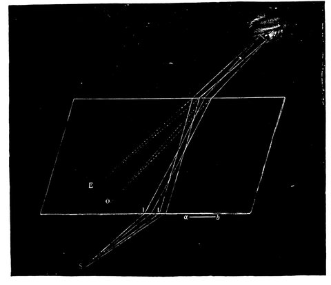
Fig. 109.—Diagram showing the path of the ordinary and extraordinary rays in a crystal of Iceland spar, producing two images apparently at E and O.
Now there is another kind of double-image micrometer which merits attention. In this case the double image is derived from a different physical fact altogether, namely, double refraction. Those who have looked through a crystal of Iceland spar, Fig. 108, have seen two images of everything looked at when the crystal is held in certain positions, but the surfaces of the crystal can be cut in a certain plane such that when looked through, the images are single. For the micrometer therefore we have doubly refracting prisms, cut in such a way as to vary the distance of the images. Generally speaking, whenever a ray of light falls on a crystal of Iceland spar or other double refracting substance, it is divided up into two portions, one of which is refracted more than the other. If we trace the rays proceeding from a point S, Fig. 109, we find one portion of the light reaching the eye is more refracted at the surfaces than the other, and consequently 228one appears to come from E and the other from O, so that if we insert such a crystal in the path of rays from any object, that object appears doubled. There is, however, a certain direction in the crystal, along which, if the light travel, it is not divided into two rays, and this direction is that of the optic axis of the crystal, A A, Fig. 110; if therefore two prisms of this spar are made so that in one the light shall travel parallel to the axis, and in the other at right angles to it, and if these be fastened together so that their outer sides are parallel, as shown in Fig. 111, light will pass through the first one without being split up, since it passes parallel to the axis, but on reaching the second one it is divided into two rays, one of which proceeds on in the original course, since the two prisms counteract each other for this ray, while the other ray diverges from the first one, and gives a second image of the object in front of the telescope, as shown in Fig. b. The separation of the image depends on the distance of the prisms from the eyepiece, so that we can pass the rays from a star or planet through one of these compound crystals and measure the position of the crystal and so the separation of the stars, and then we shall have the means of doing the same that we did by dividing our object-glass, and in a less expensive way, for to take a large object-glass of eight or ten inches in diameter and cut it in two is a brutal operation, and has generally been repented of when it has been done.
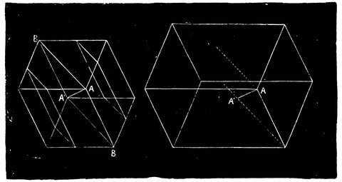
Fig. 110.—Crystals of Iceland Spar showing, A A´, the optic axis.
229It is obvious that a Barlow lens, cut in the same manner as the object-glass of the heliometer, will answer the same purpose; the two halves are of course moved in just the same manner as the halves of the divided object-glass. Mr. Browning has constructed micrometers on this principle.
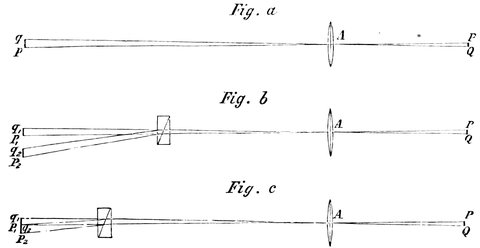
Fig. 111.—Double Image Micrometer. Fig. a, p q, single image formed by object-glass. Fig. b, p1 q1, p2 q2, images separated by the double refracting prism. Fig. c, same, separated less, by the motion of the prism.
There is yet another double-image micrometer depending on the power of a prism to alter the direction of rays of light. It is constructed by making two very weak prisms, i.e., having their sides very nearly parallel, and cutting them to a circular shape; these are mounted in a frame one over the other with power to turn one round, so that in one position they both act in the same direction, 230and in the opposite one they neutralise each other; these are carried by radial arms, and are placed either in front of the object-glass or at such a distance from it inside the telescope that they intercept one half of the light, and the remaining portion goes to form the usual image, while the other is altered in its course by the prism and forms another image, and this alteration depends on the position of the movable prism.
10. Grant’s History of Physical Astronomy, p. 454.
11. More accurately the time of transit is to be multiplied by the cosine of the star’s declination.
12. So called because the contrivance was first used to measure the diameter of the sun.
We are now, then, in full possession of the stock-in-trade of the modern astronomer—the telescope, the clock, and the circle,—and we have first to deal with what is termed astronomy of position, that branch of the subject which enables us to determine the exact position of the heavenly bodies in the celestial sphere at any instant of time.
Before, however, we proceed with modern methods, it will be well, on the principle of reculer pour mieux sauter, to refer back to the old ones in order that we can the better see how the modern instruments are arranged for doing the work which Tycho, for instance, had to do, and which he accomplished by means of the instruments of which we have already spoken.
First of all let us refer to the Mural Quadrant, in which we have the germ of a great deal of modern work, its direct descendant being the Transit Circle of the present time.
We begin then by referring to the hole in the wall at which Tycho is pointing (see Fig. 112), and the circle, of which the hole was the centre, opposite to it, on which 234the position of the body was observed, and its declination and right ascension determined. This then was Tycho’s arrangement for determining the two co-ordinates, right ascension and declination, measured from the meridian and equator. It is to be hoped that the meaning of right ascension and declination is already clear to our readers, because these terms refer to the fundamental planes, and distances as measured from them are the very A B C of anything that one has to say about astronomical instruments.
We know that Tycho had two things to do. In the first place he had to note when a star was seen through the slit in the wall, which was Tycho’s arrangement for determining the southing of a star, the sun, or the moon; and then to give the instant when the object crossed the sight to the other observer, who noted the time by the clocks. Secondly, he had to note at which particular portion of the arc the sight had to be placed, and so the altitude or the zenith distance of the star was determined; and then, knowing the latitude of the place, he got the two co-ordinates, the right ascension and declination.
How does the modern astronomer do this? Here is an instrument which, without the circle to tell the altitude at the same time, will give some idea of the way in which the modern astronomer has to go to work. In this we have what is called the Transit Instrument, Fig. 113; it is simply used for determining the transit of stars over the meridian. It consists essentially of a telescope mounted on trunnions, like a cannon, having in the eyepiece, not simple cross wires, but a system of wires, to which reference has already been made, so that the mean of as many observations as there are wires can 235be taken; and in this way Tycho’s hole in the wall is completely superseded. The quadrant is represented by a circle on the instrument called the transit circle, of which for the present we defer consideration.
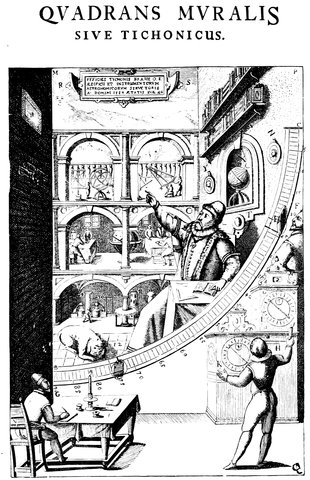
Fig. 112.—Tycho Brahe’s Mural Quadrant.
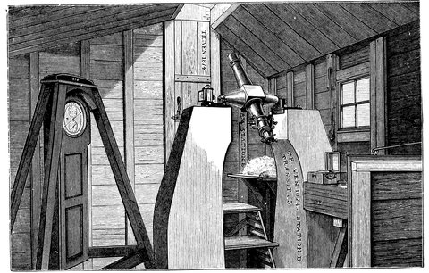
Fig. 113.—Transit Instrument (Transit of Venus Expedition).
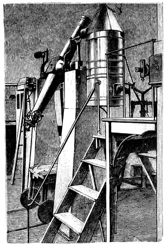
Fig. 114.—Transit Instalment in a fixed Observatory.
Now there are three things to be done in order to adjust this instrument for observation. In the first place we must see that the line of sight is exactly at right angles to the axis on which the telescope turns, and when we have satisfied ourselves of that, we must, in the second place, take care, not only that the pivots on which the telescope rests are perfectly equal in size, but that the entire axis resting on these pivots is perfectly horizontal. Having made these two adjustments, we shall at all events be able, by swinging the telescope, to sweep through the zenith. Then, thirdly, if we take care that one end of this axis points to the east, and the other to the west, we shall know, not only that our transit instrument sweeps through the zenith, but sweeps through the pole which happens to be above the horizon—in England the north pole, in Australia the south pole. 238That is to say, by the first adjustment we shall be able to describe a great circle; by the second, this circle will pass through the zenith; and by the third, from the south of the horizon to the north, through the pole. Of course, if the pole star were at the pole, all we should have to do would be to adjust the instrument (having determined the instrument to be otherwise correct) so as simply to point to the pole star, and then we should assure ourselves of the east and west positions of the axis. Some details may here be of interest.
The first adjustment to be made is that the line of sight or collimation shall be at right angles to the axis on which the instrument moves: to find the error and correct it, bring the telescope into a horizontal position and place a small object at a distance away, in such a position that its image is bisected by the central wire of the transit, then lift the instrument from its bearings or Ys, as they are called, and reverse the pivots east for west, and again observe the object. If it is still bisected, the adjustment is correct, but if not, then half the angle between the new direction in which the telescope points and the first one as marked by the object is the collimation error, which may be ascertained by measuring the distance from the object to the central wire, by a micrometer in the field of view, and converting the distance into arc. To correct it, bring the central wire half way up to the object by motion of the wire, and complete the other half by moving the object itself, or by moving the Ys of the instrument. This of course must be again repeated until the adjustment is sensibly correct.
The second adjustment is to make the pivots horizontal. Place a striding level on the pivots and bring the 239bubble to zero by the set screws of the level, or note the position of it; then reverse the level east for west, and then if the bubble remains at the same place the axis of motion is horizontal, but, if not, raise or lower the movable Y sufficiently to bring the bubble half way to its original position, and complete the motion of the bubble, if necessary, by the level screw until there is no alteration in the position of the bubble on reversing the level.
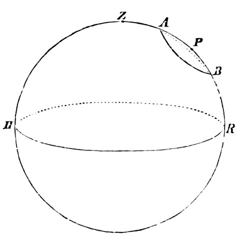
Fig. 115.—Diagram explaining third adjustment, H, R, plane of the horizon; H, Z, A, P, B, R, meridian; A and B places of circumpolar star at transit above and below pole P.
The third adjustment is to place the pivots east and west. Note by the clock the time of transit of a circumpolar star, when above the pole, over the central wire, and then half a day later when below it, and again when above it; if the times from upper to lower transit, and from lower to upper are equal, then the line of collimation swings so as to bisect the circle of the star round the pole, and therefore it passes through the pole, and further it describes a meridian which passes through the zenith by reason of the second adjustment. This is therefore the meridian of the place, and therefore the pivots are east and west. If the periods between the transits 240are not equal, the movable pivot must be shifted horizontally, until on repeating the process the periods are equal.
In practice these adjustments can never be made quite perfect, and there are always small errors outstanding, which when known are allowed for, and they are estimated by a long series of observations made in different manners and positions. The error of the first adjustment is called the collimation error, that of the second the level error, and that of the third the deviation error. When the errors of an instrument are known the observations can be easily corrected to what they would have been had the instrument been in perfect adjustment.
Now what does the modern astronomer do with this instrument when he has got it? It is absolutely without circles, but the faithful companion of the Transit Instrument is the Astronomical Clock—and the two together serve the purpose of a circle of the most perfect accuracy, so that by means of these two instruments we shall be able to determine the right ascensions of all the stars merely by noting the time at which the earth’s rotation brings them into the field of view. The clock having been regulated to sidereal time, a term fully explained in the sequel, it will show 0h. 0m. 0s. when the first point of Aries passes the meridian, and instead of dividing the day into two periods of twelve hours each, the clock goes up to twenty-four hours. If now a star is observed to pass the centre of the field of view (that is the meridian) at 1h. by the clock, or one hour after the first point of Aries, it will be known to be in 1h. of right ascension; or if it passes at 12h. it will be 12h. right ascension, or opposite to the first point of Aries, and so 241on up to the twenty-four hours, the clock keeping exact time with the earth. The transit instrument thus gives us the right ascension of a star, or one co-ordinate: and now we want the other—the declination.
This is given by the Transit Circle, which is a transit instrument with a circle attached, to ascertain the angle between the object and the pole or equator.
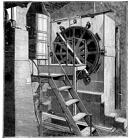
Fig. 116.—The Mural Circle.
The combination of the circle with the transit, forming the transit- or meridian-circle, is of comparatively recent date, and the earlier method was to use a circle 242with a telescope attached, fixed to a pivot moving on bearings in a wall, and called therefore the Mural Circle, Fig. 116. Since it is supported only on one side it cannot move so truly in the meridian as the transit, but, having a large circle, it gives accurate readings.
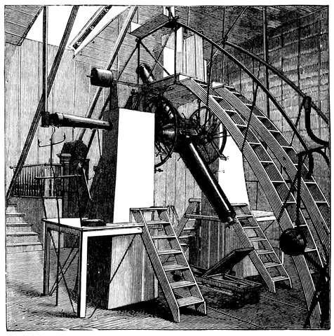
Fig. 117.—Transit Circle, showing the addition of circles to the transit instrument.
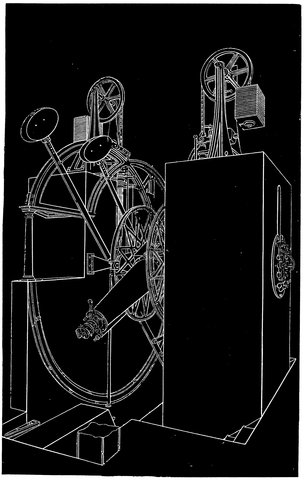
Fig. 118.—Perspective view of Greenwich Transit Circle.
Fig. 117 shows in what respect the Transit Circle is an advance upon the transit instrument and the mural circle, for in addition to the transit instrument we have the circle. This is a perspective view of the transit, and the telescope is represented sweeping in the vertical plane or meridian. In addition to the instrument resting with its pivots on the massive piers, we have the circle attached to the side of the telescope. We see at once that by means of this circle we are able to introduce the other co-ordinate of declination. If the clock 244goes true with the earth—if they both beat in unison and keep time with each other—and further if the clock shows 0h. 0m. 0s. when the first point of Aries passes the centre of the field, that is through the meridian plane, then, if we observe a star at the moment it passes over the meridian, the clock will give its right ascension and the circle its declination, when the latitude of the place is known.
The construction of the transit circle will repay a more detailed examination. A system of weights suspended over pulleys (Fig. 118) reduces the weight of the instrument on the pivots, in order that their form shall not be altered by too much friction, and on the right-hand side of one of the piers the eyepieces of the microscopes for reading the circle are shown. This is shown better in section in Fig. 119. One of the solid stone piers is pierced through diagonally, as shown at (m) (m), so that light proceeding from a gas-lamp (q) placed opposite the pivot of the telescope is allowed to fall through the openings, and is condensed by means of the lens (n) on the graduations of the circle of five minutes each, already referred to. By the side of each illuminating hole is another hole (o) (o) through which the reading microscopes, six in number, two of which are shown at (q) (p), having their eye-ends arranged in a circle at the end of the pier, are focussed on to the graduations of the circle. There is also another reading microscope, besides the six just mentioned, of less power for reading the degrees, or larger divisions of the circle. Hence from the side of the pier close to the lamp the observer can read the circle with accuracy, and measure the angle, to which we have alluded, made by the telescope when pointed to any particular star. We have now seen 245how the circle is illuminated, and now we will inquire further as to the arrangements that are necessary in order to bring this instrument into use.
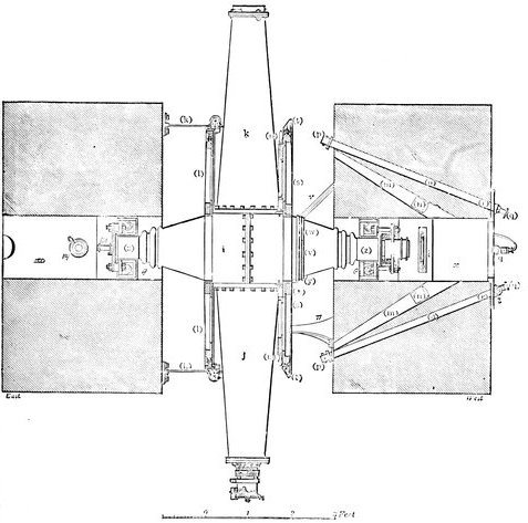
Fig. 119.—Plan of the Greenwich Transit Circle.
We must defer giving more explanation of the practical working of the instrument until we have considered the clock used in connection with it, and we shall then show how the observations are made. One important 246point to which attention should be given is the method of illuminating the wires in the eyepiece. This is the arrangement. There is a lamp at the end of one of the pivots which is hollow, the light falls on a mirror, placed in the centre of the telescope, of such a shape and in such a position that it will not intercept the light from the object-glass falling through the diaphragms on to the eyepiece. The mirror is ring-shaped, something like the brim of a hat, and is carried on two pivots, so that it can be placed diagonally in the tube, or at right angles to it; it is arranged just outside the cone of rays from the object-glass, so that when the mirror is diagonally placed the light will be grasped directly from the lamp at the end of the axis and reflected down and mixed up with the light coming from the star into the eyepiece.
In this way of course the wires can be rendered visible at night, and without such a method they would be invisible. This arrangement gives a bright field and dark wires; but there is also a method of reversing matters; for near the edge of the ring-shaped reflector are fixed prisms for reflecting the light, and when the reflector is placed square with the axis of the telescope the small prisms on the reflector send the light down through apertures in the diaphragms, so that the mirror in this position no longer sends the light down with the rays from the star, but through holes in the diaphragms themselves, to two small reflecting prisms, one on each side of the wires in the eyepiece. What has that light to do? It has simply to do this, it has to fall sideways on the wires themselves in such a manner that it does not fall on the eye except by reflection from the wires. In this way we have the means of getting a bright system of wires 247on a dark field, in which the wires and objects to be measured are the only things to be seen.
As with the pivots of the transit circle, and in fact of any astronomical instrument, so with the circles, certain fundamental points have to be borne in mind; and, although it is absolutely impossible to ensure perfection, still, to go as near to it as possible, the astronomer has to observe a great many times over in all sorts of positions in order to bring the error down to its minimum.
First, the circle must be placed exactly at right angles to the axis of the telescope, so that it is in the plane of the meridian. Secondly, the error of centering must be found. For instance, if the Greenwich circle were to be read by only one microscope, an error in the pivot or any part of the axis round which the circle turns would vitiate the readings; but we could get rid of that error, due to a fault of the axis, or to a want of centering, by means of two readings, at the extremities of a diameter; but even then we should not get rid of the possible error due to graduation, for even if the divisions on the circle were accurate at first, they would not long remain so, for the metal of which these circles are made is liable, like other metals, to certain changes due to temperature; and if a circle is very large the weight of the circle itself, supposing its form perfect when horizontal, will, when vertical, sag it down and deflect it out of shape, so that at Greenwich the method adopted is to use six reading microscopes. Fig. 120, which shows the Cambridge Transit Circle, indicates the arrangement of the five microscopes in use there, set round the circumference of the circle, much in the same manner as in the case of the Greenwich instrument, where there are holes through the 248pier in which the microscopes are placed with the eye-ends arranged in a circle at the side of it.
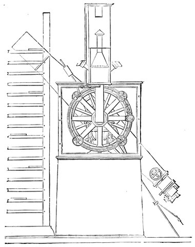
Fig. 120.—Cambridge (U.S.) meridian circle.
When, therefore, the transit is pointed to any particular star, not only is the time noted in order to determine the right ascension of the star, in a careful and elaborate way, but the readings of the circle are made by every one of these microscopes—reading from the next five minutes division of the circle which happens to be visible,—and there is an additional microscope giving the rough 249reading of the larger divisions of the circle from a certain zero.
And what, then, is this zero? There is no doubt about the reading of the zero of right ascension, it is the intersection of the two fundamental planes at the first point of Aries; but what zero shall be used in the case of the vertical circle?
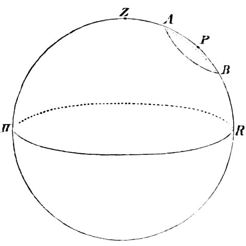
Fig. 121.—Diagram illustrating how the pole is found.
Let the circle, H, Z, R, Fig. 121, represent a great circle of the heavens, the meridian in fact, and let the centre of this circle represent the centre of the transit instrument. Now what we want is, not only to be able to measure degrees of arc along this circle, but to determine some starting-point for those degrees. One arrangement is to observe the reflection of the wires in the eyepiece of the transit circle, from the surface of mercury in a vessel which is placed below the telescope, turned with its object-glass downwards; the vessel containing the mercury is out of sight, between the two piers, but in Fig. 118 are seen the two parallel bars, with weights at the ends, carrying it, by which it may be brought into any position for the purpose referred to, so that the 250light from the wires in the eyepiece may pass through the tube and be reflected back by the mercury (the surface of which is of course perfectly horizontal), up through the tube again to the eyepiece. When the telescope is absolutely in the vertical position the images of the cross wires will be superposed over the cross wires themselves; and then an observation will give the actual reading of the circle when the instrument is pointing at 180° from the zenith; deduct 180° from this reading, and we get the reading when the instrument is pointing at the zenith—the zero required. This should be 0°, and the quantity by which it differs from 0° must be applied to the observed position of stars, so that the distance of a star from the zenith can be at once determined.
But this is not all. If we assume for the moment that the observer is at the north pole, the pole star will be exactly over head, and therefore, supposing the pole star to absolutely represent the pole of the heavens, all the observer has to do is simply to take a reading of the pole star on the arc of his circle—call it 0° O´ 0˝—and then use it as another zero to reckon polar distance from, seeing that every particular star or body we observe has so many degrees, minutes, seconds, or tenths of seconds, from the pole star.
But we are not at the north pole. Still we are in a position where the pole is well above the horizon, and from that fact we can determine the polar distance, although the absolute place of the pole is not pointed out by the pole star. Thus, if we suppose any star, A, Fig. 121, to be a certain distance from the pole, and the earth carrying the instrument to be in the centre of the circle H, Z, R, we can observe the zenith distance of that star, Z, A, when it transits our meridian above the 251pole, P; and we can then observe its distance, Z, B, when it transits below the pole; and it is clear that the difference between those two measures will give the distance A, B, or double the polar distance of that star, and the mean of the readings will give the distance, Z, P, the zenith distance of the pole, so that it is perfectly easy to determine the distance between the pole and the zenith, which, subtracted from ninety degrees, gives us the latitude of the place. It is therefore perfectly easy by means of this instrument to determine either the zenith or polar distance, and, knowing the polar distance, we get the declination, or distance from the equator, by subtracting it from ninety degrees.
In our case it is the north polar distance or declination of any object in the heavens that we record; and if we take the precaution to do so with this instrument at the time given by the clock, when the object passes the meridian, we have the actual apparent place of that body in the sky; and in this way all the positions of the stars and other bodies, and their various changes, and the courses of the planets, have been determined.
The transit circle is the most important instrument of astronomy, and such is the perfection of the Greenwich instrument that nothing could be more unfortunate for astronomy than that that instrument should be in any way damaged. And though many of us are admirers of physical astronomy, we have yet to find the instrument that is as important to physical astronomy as the transit circle at Greenwich is to astronomy of position.
The room in which these transit circles are worked—the transit room—is required to be of special construction. A clear space from the southern horizon through the zenith to the north must at any time be available; 252this entails the cutting of a narrow slit in the roof and both walls, without the intervention of any beams across the room. This slit is closed by shutters or windows which are made to open in sections, so that any part of the meridian can be observed at pleasure.
We have now to consider the way in which the transit instrument is used and the functions which both it and the transit circle fulfil.
The connection between the transit instrument and the transit clock is so intimate that either is useless without the other. In the one case we should note the passage of a star across the meridian without knowing at what time it took place; while, on the other hand, we should not learn whether the clock showed true time or not, unless we could check its indications in the manner rendered possible by transit observations. In what has been already said of time we referred to it as measured by our ordinary clocks, i.e. reckoning it from noon to midnight and midnight to noon, and regulated entirely by the length of the solar day. It would at first sight seem that it should be twelve o’clock by a clock so regulated when the sun passes the meridian; but the earth’s orbit is not circular, and the sun’s course is inclined to the equator, so that, as determined by such a clock, sometimes he would get to the meridian a little too late, and sometimes too early, so that we should 254be continually altering our clocks if we attempted to keep time with the sun.
One of the greatest boons conferred by astronomy upon our daily life is an imaginary sun that keeps exact time, called the Mean Sun, so that the mean sun is on the meridian at twelve o’clock each day by our clocks, regulated by the methods we have now to discuss. Such clocks regulated, as it is called, to mean time are sometimes a few minutes before, and at others a few minutes behind the true sun, by an amount called the Equation of Time, which is given in the almanacs. It would therefore be difficult to regulate our standard clock by the sun, so we do it through the medium of the stars, which go past our meridian with the greatest regularity, since their apparent motion depends almost wholly upon the equable rotation of the earth on its axis, while the apparent motion of the sun is complicated by the earth’s revolution round it.
This method at first sight is complex, and in fact we cannot obtain mean time directly by such transits of stars. It is accomplished indirectly by means of a clock set to star- or sidereal-time, and such a clock is the astronomer’s companion, to which he always refers his observations, and the indications of which alone are always in his mind. This he calls the Sidereal Clock.
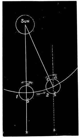
Fig. 122.—Diagram illustrating the different lengths of solar and sidereal day.
We have, then, next to consider the difference between the clock used for the transit, or the sidereal clock, and an ordinary solar clock, or between a solar and a sidereal day. Let S, Fig. 122, represent the sun, and the arc a part of the orbit of the earth, the earth going in the direction of the arrow. Let 2 represent the position of the earth one day, and let 1 represent the position of the earth on the day before. A line drawn from the sun through the earth’s centre will give us the places a, b, on the earth at which it is midday on the side turned towards the sun, and midnight on the side turned from the sun. Now when a revolution of the earth with reference to the stars has been accomplished the earth comes to the second position, 2; and c is the point of midday; and there is a certain angle here between a and c, through which the earth must turn before it is noon at a, due to the change of position of the earth, or to the apparent motion of the sun among the stars, by which the sun comes to the meridian rather later than the stars each day. Now let us suppose that, while one observer in England is observing the sun at midday, another is observing the stars at the antipodes at midnight, the star is seen in the direction ⁎. We are aware that the stars are so far away, that from any point of the earth’s orbit they seem to be in absolutely the same place—they do not 256change their positions in the same way as the sun appears to do amongst them—an observer at b therefore sees on his meridian the star ⁎ while the observer at a sees the sun on his meridian; supposing b to represent the same observer, on the second day, he will see the star due south before the other observer at a sees the sun due south. The result of that is, that the sidereal day is shorter than the solar day, and the sun appears to lose on the stars. If we wish to have a clock to show 12 o’clock when the sun is southing, we shall want it to go slower by nearly four minutes a day than one which is regulated by the stars and is at 12 o’clock when our starting-point of right ascension—which is the intersection of those two fundamental planes, the equator and the ecliptic—passes over the meridian.
One of the uses of the clock showing sidereal time in connection with the convenient fiction of the “Mean Sun,” is to give to the outside world a constant flow of mean time regulated to the average southing of the sun in the middle of the period for which the sun is above the horizon each day in the year.
The stellar day, that is the time from one transit of a star to the next, is shorter than a solar day by 3m. 56s., so what is called sidereal time, regulated by the transits of well-known stars, in the manner we shall presently explain, by no means runs parallel with mean time so far as the clock indications go. Indeed when we look at a sidereal clock, we see something different to the clock we are generally accustomed to see. In the first place, we have twenty-four hours instead of twelve, and then generally there is one dial for hours, another for minutes, and another for seconds. That of course might happen in the case of the mean-time clock; but the 257mean-time clock is not often divided into twenty-four hours, although it formerly used to be, as the dials in Venice still testify.
We now see the importance of an absolutely correct determination of the right ascension of stars; for this right ascension, expressed in hours, minutes, and seconds, is nothing more nor less than the time indicated by the sidereal clock, by the side of the transit instrument, when a star passes over, or transits, the central wire of that instrument. Hence it is the sidereal clock which keeps time with the stars, and which we keep correct by means of the transit instrument.
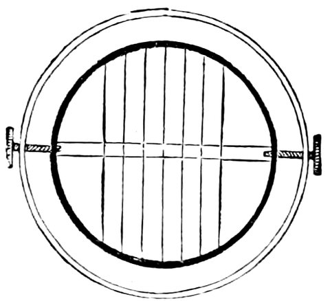
Fig. 123.—System of wires in transit eyepiece.
Let us show how this was always done some twenty or thirty years ago, and how it is sometimes done now. The transit room is kept so quiet that one can hear nothing but the ticking of the sidereal clock; the star to be observed is then carefully watched as it traverses the field of view over the wires, and the time of transit over each wire is estimated to the tenth of the time between each beat by the observer.
We reproduce in Fig. 123 a rough representation of what is seen in the field of view of a transit instrument. Now if we could be perfectly sure of making an accurate observation by means of the central 258wire, it is not to be supposed that astronomers would ever have cared to use this complicated system of wires in their eyepieces; but so great is the difficulty of determining accurately the time at which a star passes a wire, that we have in eyepieces introduced a system of several wires, so that we may take the transit of the star first at one wire, then at another, until every wire has been passed over.
We want one wire exactly in the middle to represent the real physical middle of the eyepiece so far as skill can do it, and then there is a similar number of wires on either side at exactly equal distances; so that the average of all the observations made at each of the wires will be much more likely to be accurate than a single observation at one wire. In this way the astronomer gives himself a good many chances against one to be right. If he lost his chance from any reason when using only one wire, he would have to wait twenty-four more sidereal hours before he could make his measure again, but by having five, or seven, or twenty-five or more wires in the eyepiece of the telescope, he increases his chances of correctness: and the way in which he works is this: While the heavens themselves are taking the stars across the wires he listens to the beating of the clock. If a star crosses one of the wires exactly as the clock is beating, he knows that it has passed the wire at some second, and he takes care to know what second that is; but if, instead of being absolutely coincident with one of the beats of the clock, it is half-way between one beat and another, or nearer to one beat than another, he estimates the fraction of a second, and by practice he has no difficulty at all in estimating divisions of time equal to tenths of a second, and at each 259particular wire in the eyepiece the transit of the star is thus minutely observed.
Then if the observations are complete and the mean of them is taken, it should, after the necessary corrections for instrumental errors have been applied, give the actual observation made at the central wire; if the astronomer cannot make observations at every wire, he introduces a correction in his mean to make up for the lost observations.
This is what is called the “eye and ear” method, because the observer is placed with his eye to the telescope, and he depends upon his ear to give him the exact interval at which each beat of the clock takes place, and he requires an exact power of mentally dividing the distance between each beat into ten equal parts, which are tenths of seconds. In this method of observation every observer differs slightly in his judgment of the instant that the star crosses the wire, and his estimation differs from the truth by a certain constant quantity which he must always allow for; this error is called his personal equation.
In this way then the transit instrument enables us, having true time, to determine the right ascension of a heavenly body as it transits the meridian, and, knowing the right ascension of a heavenly body, we have only to watch its transit in order to know the true time; so if the observer knows at what time a known star ought to transit, he has an opportunity of correcting his clock.
So much for the eye and ear method of transit observation. There is another which has now to a very large extent superseded it. This is called the “chronographic method”; we owe it to Sir Charles Wheatstone, who made it possible about 1840.
260Figs. 124-7 are from drawings of the chronograph in use at Greenwich, and by their means we hope to make the principle of the instrument clear. In this chronograph, g is a long conical pendulum which regulates the driving clock in the case below it, through the gearing of wheel-work, as it turns the cylinder, E, gently and regularly round. On the cylinder is placed paper to receive the mark registering the observations; along the side of the cylinder or roller run two long screws, K and N, Fig. 125, which are also turned by the clock, and on them are carried electro-magnets, A, B, Fig. 125, and prickers, 35, Fig. 126; as the screws turn, the magnets and prickers are moved along the roller, and, as the roller turns, the pointer, 36, Fig. 127, traces a fine line on the paper like the worm of a screw on the surface; and it is close to this line, which serves as a guide to the eye, that the prickers make a mark each time a current is sent through the electro-magnets; this turns each of them into a magnet, and they then attract a piece of iron which, in moving upwards, presses down its pricker by means of a lever, and registers the instant the current is sent.
The different wires are brought, first from the transit circle to work one pricker, and then from the clock to work the other, the clock sending a current and producing a prick on the roller every second.
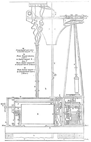
Fig. 124.—The Greenwich chronograph. General view.
The observer, instead of depending upon the eye and ear as he had to do before, has then the means of impressing a mark at any instant upon the same cylinder, in exactly the same way that the pendulum of the clock impresses the mark of any second, so that as each wire in the eyepiece of the transit instrument is passed by the star, he is able, by the same method as the clock, to record on this same revolving surface each 262observation, which can afterwards be compared with the marks representing the seconds, and so the exact time of each observation is read off more accurately and with less trouble than by the old method. Let us suppose we are making a transit observation: the clock will be diligently pricking sidereal seconds, while we, by a contact-maker held in the hand, are as diligently recording the moments at which the star passes each wire.
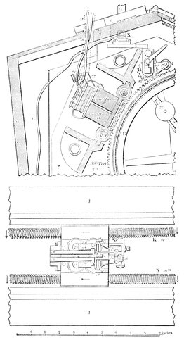
Fig. 125.—Details of the travelling carriage which carries the magnets and prickers. Side view and view from above.
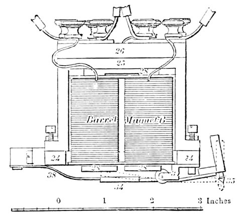
Fig. 126.—Showing how on the passage of a current round the soft iron the pricker is made to make a mark on the spiral line on the cylinder.
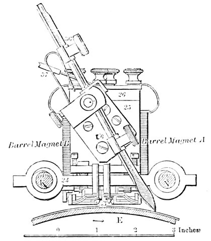
Fig. 127.—Side view of the carriage carrying the magnets and the pointer that draws the spiral.
264This is done by pressing a stud, and sending a current at each transit; so that we shall have a dot in every other space between the clock dots, supposing the wires to be two seconds in time apart; supposing them to be three seconds apart, our dots will be in every third space; supposing them to be four seconds apart, our dots will be in every fourth space, and so on; and tenths and hundredths of seconds are estimated, by the position of each transit dot between those which record the seconds.
In this way one sees that we have on the barrel an absolute record, by one of the pointers, of the seconds recorded by the clock, and, by the other, of the exact times at which a star has been seen at each wire of the transit instrument.
Now of course what is essential in this method is that there shall be a power of determining not only the precise second or tenth of a second of time, but also the minute at which contact takes place, otherwise there would be a number of seconds dots without knowing to what minute they corresponded; it would be like having a clock with only a second-hand and no minute-hand.
The brass vertical sliding piece shown at the lower left-hand side in Fig. 96, carries at its upper end two brass bars, each of which has, at its right-hand extremity, between the jaws, a slender steel spring for galvanic contact; the lower spring carries a semicircular piece projecting downwards, which a pin on the crutch rod lifts in passing, bringing the springs in contact at each vibration: the contact takes place when the pendulum is vertical, and the acting surfaces of the springs are, one platinum, the other gold; an arrangement 265that has been supposed to be preferable to making both surfaces of platinum. By means of the screws n and o, which both act on sliders, the contact springs can be adjusted in the vertical and horizontal directions respectively. Other contact springs in connection with the brass bars p and q, on the other side of the back plate, are ordinarily in contact, but the contact is broken at one second in each minute by an arm on the escape-wheel spindle. The combination of these contacts permits the clock to complete a galvanic circuit at fifty-nine of the seconds in each minute, and omit the sixtieth.[13]
In this way we may suppress the sixtieth second, thus leaving a blank that marks the minute; and all that the observer has to do after he has made a record of the transit, is to go quietly to the barrel, and mark the hour and minute in the vacant space. A barrel of this size will contain the observations which would be made in some hours; so that at the end of that time it may be taken off, and it will give, with the least possible chance of error, a permanent record of the work of the astronomer.
It is at once apparent that by the introduction of this application of electricity, astronomy has been an enormous gainer; but so far we have simply given a description of one instrument which has been suggested for that purpose. A few words may be said on other forms.
In the instrument used in the Royal Observatory at Greenwich the rotation of the roller is kept uniform, as we have seen, by a conical pendulum; but there are other methods of attaining this end—there is the fly-wheel and fan, similar to the arrangement for regulating the striking 266part of a clock; there is the governor used for the steam-engine, and others which give a fairly regular motion—for the motion need not be absolutely uniform, because the dots, which form the points from which to measure, are made by the standard clock.
The particular instant at which each minute occurs may be recorded in another way. The two steel springs above described may be pressed together, not by a pin in the crutch, but by cogs on a wheel attached to the spindle of the escape-wheel of the clock (see Fig. 128); and then all we have to do to stop the transmission of a current at the sixtieth second is to remove one of the cogs.
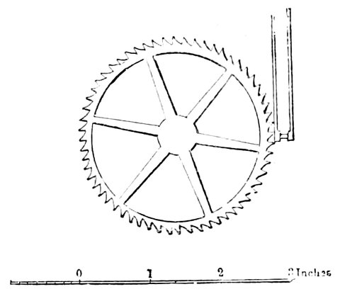
Fig. 128.—Wheel of the sidereal clock, and arrangement for making contact at each second.
Another simple method for transmitting seconds’ currents has also been occasionally tried. A wire runs down the whole length of the pendulum, and ends in a projection of such a length that it swings through a small globule of mercury in a cup below it, the pendulum being connected with one wire from the chronograph and the mercury with the other; thus there will be a making and breaking of contact each time the point of the pendulum swings through the mercury. It is 267uncertain which method is the better; one would prefer that which, under any circumstances, could disturb the pendulum least: but as to which this is opinions differ.
We have now described the modus operandi of making time observations with the transit instrument, the final result of which is that the time shown by the sidereal clock corresponds with the right ascension of the “clock stars” as they transit the central wire.
The great use, as we have already stated, made of the sidereal clock thus kept right by the stars is to correct the mean-time clock with a view of supplying mean solar time to the outside world.
As the sidereal clock is regulated by the stars, it can be corrected by them at any time by the clock stars given in the “Nautical Almanac,” whose time of passing the meridian is calculated beforehand much more accurately than a mean-time clock could be corrected by the sun; we therefore correct our mean clock by the sidereal, the two agreeing at the vernal equinox, when the sun is in the first point of Aries, and the sidereal clock gaining about 3m. 56s. each day until it has gained a whole day, and agrees again at the next vernal equinox.
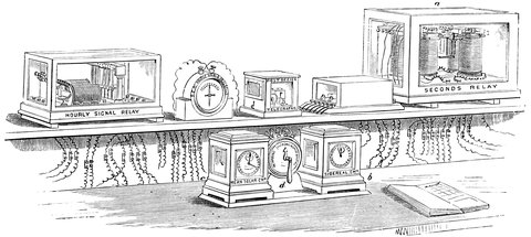
Fig. 129.—Arrangement for correcting mean solar time clock at Greenwich.
At Greenwich there is, as we have already seen, a standard, sidereal clock, that is, a clock keeping sidereal time; and regulated from this is the standard solar time clock, giving the time by which all our clocks and watches are governed. In practice at Greenwich the solar clock is regulated as follows: in the computing room are two chronometers, c and b, Fig. 129, the one, c, regulated electrically by the mean-time clock, and the other, b, regulated by the sidereal clock—the error of the latter being known by transit observations of stars on 269the Nautical Almanac list, the difference between the observed time of transit and the right ascension of the star being the error required. The proper difference between the two clocks is then calculated and the error allowed for, which shows whether the solar clock is fast or slow; to correct it the following method is adopted: Carried on the pendulum of the solar clock is a slender bar magnet, about five inches long, and below it, fastened to the clock-case, is a galvanic coil; the magnet passes at each swing over the upper end of the coil; if now a current is sent through this coil in one direction repulsion takes place between the magnet and coil, and the clock is slowed; if, on the other hand, the current is reversed, the clock is made to gain. Now between the two chronometers is a commutator, d, which, by moving the handle to one side or the other, sends the current through the coil in such a manner that the clock is accelerated or retarded sufficiently to set it right; when the handle of the commutator is in the position shown in the drawing no action takes place. As an instance of another method of regulating one clock from another, we will quote what Professor Piazzi Smyth says of the clock arrangements at Edinburgh.
Correction of Mean-time Clock.—“First get its error on the observing, i.e. sidereal clock. This is always done by coincidence of beats, safe and certain to within one-tenth of a second, and with great ease and comfort by means of the loud-beating hammer which strikes the seconds of the sidereal clock on the outside of the case; one can then watch the neck-and-neck race which takes place every six minutes between the second of a sidereal clock and the second of a mean-time clock, the former always winning while you look at 270the motion of the mean-time seconds hand, and hear the seconds of the sidereal time.
Having got the error, say three (0·3)-tenths of a second slow, this is the arrangement for correcting it. The pendulum is suspended by a spring extra long, and a long arm goes across the clock pier, and the pendulum spring passes through a fine slit in the middle of it, and the left end (of said arm) turns on a pivot, while the right end rests on a cam, which can be turned by a handle outside the clock-case. Turning the handle one way raises the arm, and with that lengthens the acting length of the pendulum spring, and turning the other way, lowers it and shortens the pendulum, but so slightly that it takes fifteen minutes of the quickened rate of the pendulum, when shortened, to add the required 0·3 seconds to the indications of the clock.”[14]
The sidereal clock is used in many ways besides the purpose of giving a basis from which we can at any time get solar time, the distribution of which forms the subject of our next chapter.
13. Nature, April 1, 1875.
14. This plan was devised and executed by Mr. Sang, C.E., Edinburgh.
We have now described the method of obtaining and keeping true Greenwich time by means of transit observations, and the next thing is to distribute it either by controlling or driving other clocks electrically, or by sending electric signals at known times for persons to set their clocks right.
Nearly all, if not quite the whole, of the mean-time clocks in the Observatory are driven by a current controlled by the standard clock, as also is a seconds relay, a Fig. 129. The clock controls, by currents sent every second by the relay, one or two clocks in London, by special wires.
So long ago as the year 1840 Sir Charles Wheatstone read a paper before the Royal Society in which he described an apparatus for controlling any number of clocks by one standard clock at a distance away. The principle was, that at each beat of the standard clock an electric current was sent from it through a wire to the clocks to be worked by it or governed; and this current made an electro-magnet attract a piece of iron each time it was sent; and this piece of iron moved backwards and forwards two pallets, something like those of an ordinary 272clock, which turned a wheel, and so worked the clock. Instead of a spring or weight being used to work it regulated by the pallets, the pallets moved the clock themselves, and of course keep time with the standard clock. Sir Charles Wheatstone in this most valuable pioneer paper, indicates several modifications of this plan. He proposed to the Astronomer-Royal to test his method by using the then new telegraph line to Slough, but the idea was not carried out.
This method of driving clocks by electricity naturally required considerable battery power, and in the more modern systems the clocks are simply controlled, and not driven, by electric currents.
A very pretty method of regulating clocks by a standard clock is that in use at Edinburgh. On the pendulum rod of the clock to be regulated, and low down on the same, is a coil of fine covered wire wound round a short tube. Two permanent magnets are placed in line with each other, with their N or S ends close together and the other ends attached to the clock-case, in such a manner that the coil, on swinging with the pendulum, can slide over the magnets without touching. The terminal wires of the coil are led up to near the point of suspension of the pendulum, so as not to affect its swing, and the regulating current is sent through a wire like a telegraph wire from the standard clock, and from this wire round the coil and then to the earth, or back by another wire. Currents are sent through the wires in contrary directions during each successive second, so that the current in the coil flows in one direction during its swing from, say, right to left, and in the contrary direction when swinging from left to right; the effect of the current flowing in one direction is to cause one 273magnet to repel the coil off it, and the other to attract it over it, so that there is a tendency to throw the coil from one side of its swing to the other, and back again when the current is reversed. A little consideration will make it clear that if the pendulum tries to go too fast the coil will tend to commence its return swing before the current assisting the previous swing has stopped, and it will therefore meet with resistance, and be brought back to correct time.
The alternate currents during each second may be sent by having a wheel of thirty long teeth on the axis of the seconds hand. Above the wheel, and insulated from each other, are fixed two light springs which descend side by side on either side of the teeth of the wheel, and at right angles to each spring there projects sideways a little bar of agate with sloping sides, which is lifted up by the teeth as they pass; one agate is fastened a little lower down its spring than the other, so that they are held one above the other, and half the distance between two teeth apart: the wheel is so arranged that while at rest one of the teeth presses against one of the agates and pushes the spring outwards, while the other agate drops between two teeth. At the next tick of the clock the wheel will move one-half a tooth’s distance and the other agate will be raised and the first dropped. At the bottom of each spring is a little platinum knob that is brought against a platinum plate as each spring is raised, so as to make electric contact. Two batteries (single cells of “sawdust-Daniell’s” answer admirably for short distances) are used, the + pole of one being put in contact with the upper attachment of one spring and the - pole of the other battery in contact with the other spring. The other poles are put 274to earth, or connected to the return wire from the governed clock. The plate against which the springs are lifted is put in connection with the line wire going to the regulated clock. Then, as either spring is lifted up during the swing of the pendulum from side to side, a + or - current is sent through the line wire from one of the batteries. It is not absolutely necessary to use two batteries, one being sometimes sufficient, and in this case one spring is thrown out of action, and a current sent only during every other second in the same direction. The battery may in this case be placed close to the regulated clock, or anywhere in the circuit, so long as a current flows whenever the standard clock completes the circuit at the other end. This method has the advantage that the amount of current sent can be regulated at will by a person at the regulated clock, so that it is possible by putting on more battery power to get sufficient current through the wire to work a bell ringing at every other second, or a galvanometer, showing when the seconds hand of the standard clock is at the Os, for there is one tooth cut from the wheel in such a position that when the seconds hand is at Os no current is sent for two or more following seconds according as one or both springs are acting; knowing this, the observer watches for the first missing current or “dropped second,” and so finds if his clock is being correctly regulated.
We see now the necessity for correcting the standard clock by gradually increasing or decreasing the rate, for if it were done rapidly, the controlled clocks would break away from the control, and not be slowed and accelerated with the standard. At Greenwich the correction, usually only a fraction of a second, is made a little before the hours of 10 A.M. and 1 P.M., since at 275those instants a distribution of time is made throughout the country. This distribution is made as follows:—
An electric circuit is broken in two places at the standard clock, one place of which is connected for some seconds on either side of each hour, while the other is connected at each sixtieth second; both breaks can therefore be only connected at the commencement of each hour, and then only can the current pass. We will call this, therefore, the hourly current: it acts on the magnet discharging the Greenwich time ball at one o’clock daily, and on the magnet of the hourly relay shown in Fig. 129, which completes various circuits. One goes to the London Bridge station of the South-Eastern Railway Co., and the other to the General Post Office for further distribution. The bell and galvanometer in the figure marked “S. E. R. hourly signal and Deal ball,” and “Post Office Telegraphs” show the passage of these signals. We have now got the hourly signal at the Post Office, and this is distributed by means of the Chronopher, or rather Chronophers, for there are two, the old one originally constructed by Mr. Yarley, and brought from Telegraph Street on the removal to St. Martin’s-le-Grand, and a new one, much larger, shown in the accompanying Fig. 130. It is to this that the Greenwich wire is led, and the current transmitted to the different lines. The lines are divided into four groups, (1) the metropolitan, (2) short provincial, (3) medium provincial, (4) long provincial; the first being wires passing to points in London only, the second to places within about 50 miles of London, the third to more distant places, and the fourth to the more distant places still, requiring signals. The ends of each of the four groups are brought together, and each group has its separate relay. These 276four relays—the left-hand four shown in Fig. 130—are all acted upon by the Greenwich signal and therefore act simultaneously, each relay sending a portion of the current of its battery through each wire of its group.
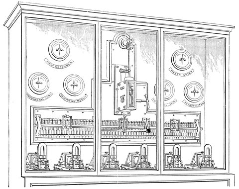
Fig. 130.—The Chronopher.
277The metropolitan group, being used only for time purposes, is always connected with the relay, but to the country, signals are sent only twice a day, namely, at 10 A.M. and at 1 P.M., and as the ordinary wires are used for this purpose, they must be switched into communication with Nos. 2, 3, and 4 relays. The action at each hour is as follows:—The wires leading to the respective towns are connected with their speaking instruments through a contact spring; these contact springs are shown in the figure in a row, like the keys of a piano; along the keys runs a flat bar which at a short time before 10 A.M. and 1 P.M. is turned on its axis by the clockwork above, by so doing it presses back all the keys from their respective studs, and so cuts off communication with the speaking instruments, and puts the wires into communication with the bar, which is divided into three insulated portions, each in communication with a relay and battery; the batteries and relays become connected with their respective groups, and a constant current flows through all the wires to the distant stations serving as a warning. When the Greenwich current arrives the relays reverse the currents, and this gives the exact time. Shortly afterwards the clock turns back the rod and the springs go into contact with their respective instruments, and all goes on as before. One of the remaining relays of the apparatus sends a current to Westminster clock tower for the rating of the clock there, but it is in no way mechanically governed by the current. The apparatus is entirely automatic, and to judge of the 278degree of accuracy obtained an experiment was made. One of the distributing wires was connected with a return wire to Greenwich, and the outgoing current to the Post Office and the incoming one were passed round galvanometers, when no sensible difference could be seen in the indications.
At 10 A.M. a considerable distribution goes on by hand. At this instant a sound signal is heard from the chronopher, and the clerks immediately transmit signals through the ordinary instruments to some 600 places; these again act as centres distributing the time to railway stations and smaller places.
The methods of signalling the time are various; at some places, as at Edinburgh, Newcastle, Sunderland, Dundee, Middlesborough, and Kendal, a gun is fired at 1 P.M. The history of the introduction of time-guns is a somewhat curious one.
In August 1863, during the meeting of the British Association at Newcastle, Mr. N. J. Holmes contrived the first electric time-gun. This gun was fired by the electric current direct from the Royal Observatory at Edinburgh, 120 miles distant. Time-guns were afterwards experimentally fired at North Shields and Sunderland; the Sunderland gun was after a time withdrawn; the Newcastle and North Shields time-guns are regularly fired every day at 1 P.M. Four time-guns were mounted in Glasgow, also to be fired by the electric current from Edinburgh; a large 32-pounder was placed at Port Dundas, on the banks of the Forth and Clyde Canal; a second small gun was placed near the Royal Exchange; a third 18-pounder at the Bromielaw, for the benefit of Clyde ships in harbour; and a fourth twenty-five miles further down the Clyde, at the Albert Quay, Greenock, for the 279vessels anchored off the tail of the bank. These four guns, and the two at Newcastle, were regularly fired from the Royal Observatory, Edinburgh, for some weeks. A local jealousy springing up amongst a few of the Glasgow College Professors and the Edinburgh Observatory, against the introduction of mean-time into Glasgow from the Royal Observatory Edinburgh, instead of deriving it from the Glasgow Observatory clock (the longitude of which was undetermined at that time), the originator of the guns, Mr. Holmes, was cited before the police-court, charged under the Act with discharging firearms in the public streets. The jealousy ended in the withdrawal of the guns, and Glasgow, from then until now, has been without any practical register of true time.[15]
Another system of time signalling is to expose a ball to view on the top of a building, and drop it, as in the case of the ball automatically dropped at Greenwich every day. We have already mentioned that one of the wires from the Greenwich Observatory connects it with the London Bridge Station, and this is used for dropping the time-ball at Deal. In return for the hourly signals the Company give up the use of the wires to Deal for two or three minutes about 1 P.M., when the Deal wire is switched into communication with the Greenwich wire by a clock, just in the same manner as at the Post Office, and communication is also made at Ashford and Deal, in order that the current shall go to the time-ball. In order that they shall know at Greenwich that the ball has fallen correctly, arrangements are made so that the ball 280on falling sends a return current back to Greenwich. It appears that erroneous drops are rare, but, if such is the case, a black flag is immediately hoisted and the ball dropped at 2 P.M.
Hourly signals are distributed on the metropolitan lines and to the “British Horological Institute” for Clerkenwell; the leading London chronometer makers also receive them privately.
We now come to deal with one of the practical uses of the clock and transit instrument with reference to determining longitudes.
The earth rotates once every twenty-four hours, and if at any time a star is directly south of Greenwich it is also due south of all places on the meridian of Greenwich north of the equator, and north of all places on the same meridian south of the equator; then, as the earth rotates, the meridian of Greenwich will pass from under the star, and others to the west will take its place, and in an hours time, at 1 P.M., a certain meridian to the west of Greenwich will be under the star, and in that case all places on this meridian will be an hour west of Greenwich, and so on through all the twenty-four hours, the meridian being called so many hours, minutes, or seconds, west, as it passes under any star that length of time after the meridian of Greenwich. It is immaterial whether we reckon longitude in degrees or in time, for since there are 360 degrees or twenty-four hours into which the equator is divided, each hour corresponds to 15°. We also express the longitude of a place by its distance east of Greenwich in hours, so instead of calling a place twenty-three hours west, it is called one hour east. Suppose we wish to find the longitude of any place, all that is required to be known to an observer 281there is the exact time that a certain star is on the meridian of Greenwich; he then observes the time that elapses before the star comes to his meridian, and this time is the longitude required.
This, of course, only shows the principle, for in practice it is not absolutely necessary for the star to be on either meridian, provided its distance on either side is known, when, of course, the difference between the times when it actually crosses the meridian can be reckoned.
In practice a difficulty arises in finding out at a distance from Greenwich what time it is there. It is of course twelve o’clock at Greenwich when the sun crosses the meridian, and it is also twelve o’clock at all the other places when the sun crosses their meridian: but if a place is two hours west of Greenwich, the sun crosses the meridian two hours later than it does at Greenwich, and consequently their clock is two hours slower than Greenwich time, hence the term “local time,” which is different for different places east or west of Greenwich. We have taken above a star for our fixed point, but obviously the sun answers the same purpose.
It will appear from this, that if we know the difference between the local times of two places, we also know the longitude of one place from the other, which is the same. A great number of ways have been tried in order to make it known at one observing station what time it is at the other. Rockets are sent up, gunpowder fired, and all kinds of signals made at fixed times for this purpose; but these, of course, only answer for short distances, so for long ones carefully adjusted chronometers have to be carried from one station to the other to convey the correct time; unless telegraph wires 282are laid from one place to another, as from England to America; then it is easy to let either station know what time it is at the other. For ships at sea chronometers answer well for a short time, but they are liable to variation.
There are certain astronomical phenomena the instant of occurrence of which can be foretold—and published in the nautical almanacs—such as the eclipses of Jupiter’s moons, and the position of our own moon amongst the stars. Suppose then an eclipse of one of Jupiter’s moons is to take place at 1 P.M. Greenwich time, and it is observed at a place at 2 P.M. of the observer’s local time, i.e., two hours after the sun has passed his meridian, then manifestly the clock at Greenwich is at 1 P.M. while his is at 2 P.M., and the difference of local time is one hour, and the place is one hour, or 15°, east of Greenwich. If, however, the eclipse was observed at 12 noon, then the place must be one hour west of Greenwich. The local time being one hour slower than Greenwich shows that the sun does not south till an hour after it does at Greenwich, or, in reality, the place does not come under the sun till after the meridian at Greenwich has passed an hour before, clearly showing it to be west of Greenwich.
We shall now see how easy it is to find the longitude when the two stations are electrically connected. Suppose we wish to determine the difference of longitude of two places in England,—this can be determined with the utmost accuracy in a short time if the observers have a chronograph, of the kind just described, to record the transit of a star at these two places. The observers at each station arrange that the observer at Station A shall observe the transit of a certain star on his chronograph, 283and the observer at Station B shall observe the transit of the same star on his, and then with the faithful clock, beating seconds and marking them on the surface of both chronographs simultaneously, the difference of sidereal time between the transit of the same star over Station A and Station B will be an absolute distance to be measured off in as delicate a way as possible by comparison of the roller of each chronograph, and will give exactly how much time elapses between the two transits. This is the longitude required. There are various methods of utilizing the same principle, as, for instance, one chronograph only may be used, and both observers then register their transits on the same cylinder. But when we have to deal with considerable distances, such as between England and the United States, then we no longer employ this method. From Valentia we telegraph to Newfoundland in effect “Our time is so-and-so,” and then the observer at Newfoundland telegraphs to Valentia “Our time is so-and-so.”
In this way the absolute longitude of the West of Ireland and America and the different observatories of Europe has been determined with the greatest accuracy.
So it appears there are two methods, the first showing one time, say Greenwich time, at both places, and showing the difference in times of transit of stars; or secondly, having the clock at each place going to its own local time, so that a certain star transits at the same local time at each place, and finding the difference between the two clocks.
15. It was found, that between the passing of the spark into the gun, and the ignition of the powder and discharge of the piece, one tenth of a second elapsed.
In former chapters we have described the transit circle as it now exists as the result of the thought of Tycho, Picard, Römer, and Airy. This, though the fundamental instrument in a meridional observatory, is by no means the only one, and we must take a glance at the others.
In Römer’s “Observatorium Tusculaneum,” near Copenhagen, built in 1704, there was not only a transit circle in the meridian of course, but a transit instrument in the prime vertical, i.e. swinging in a vertical plane at right angles to the former one, so that while the optical axis of one always lies in a N.S. plane, that of the other lies in an E.W. one. Römer did not use this instrument much; it remained for the great Bessel to point out its value in determinations of latitude.
This instrument is, so to speak, self-correcting, because between the transit of a star over its wires while pointing to the east of the meridian, and that while pointing to the west its telescope can be reversed in its Ys, or one position may be taken for one night’s observations, and the other for the next, and so on.
285In Struve’s form of this instrument the transit of stars can be observed at an interval of one minute and twenty seconds, this time only being required to raise it from the Ys, to rotate it through 180°, and lower it again. This rapid reversal, and consequent elimination of instrumental imperfections, enable observations of the most extreme precision to be made in such delicate matters as the slight differences of declination of stars due to aberration, nutation, and the like.
The intersection of the meridian with the prime vertical marks the zenith. To determine this:—first, there is the zenith sector, invented by Hooke; it consists of a telescope, carried by an axis on one side of the tube, and at right angles to it, so that the telescope swings exactly as a transit does, and it is provided with cross wires in the same manner; instead, however, of having a whole circle, it has only two segments of a circle; and as it is never required to swing the telescope far from its vertical position, there is a diagonal reflector at the eyepiece, so that the observer can look sideways, instead of upwards, in an awkward position. Its use is to determine the zenith distance of stars as they pass near that point. These distances are read off on the parts of the circle by verniers or microscopes, as in the transit circle. The zenith telescope, chiefly designed by Talcott, is the modern equivalent of the sector, and both instruments are more used in geodetical operations than in fixed observatories. At Greenwich, however, there is an instrument for determining zenith distances of very special construction. This is called the reflex zenith tube, shown in Fig. 131. It is a sectional drawing of one of those instruments showing the path of the rays of light. A, B, is an object-glass, 286fixed horizontally, and below it is a trough of mercury, C, the surface of which is always of course horizontal. The light from a star near the zenith is allowed to fall through the object-glass, which converges the rays just so much that they come to a focus at F, after having been reflected from the surface of the mercury, and also by the diagonal mirror or prism, G; at F, therefore, we have an image of the star, which can be examined together with the cross-wires at the eyepiece, M. There is in this instrument no necessity for the accurate adjustments that there is in the case of the transit, the surface of the mercury being always horizontal, and so giving an unaltering datum plane.
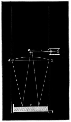
Fig. 131.—Reflex Zenith Tube.
287When the star is perfectly vertical, its image will fall on a certain known part in the eyepiece; but, as it leaves the vertical, the angle of incidence of its light on the mercury alters, and likewise that of reflection, so that the position of the image changes, and this change of position in the eyepiece is measured by movable cross-wires and a micrometer screw, similar to that employed for reading the circle in the transit circle.
At the present time γ Draconis is the star which passes very nearly through the zenith of Greenwich, and observations of this star are accordingly made at every available opportunity.
We now pass to an enlargement of the sphere of observation of the transit circle in order that any object can be viewed at all times when above the horizon; in this case the transit circle passes into the alt-azimuth, or altitude and azimuth instrument, astronomical theodolite, or universal instrument.
A reference to Fig. 132—a woodcut of an ordinary theodolite—will show the new point introduced by this construction.
Imagine the upper part of the theodolite fixed with its telescope and circle in the plane of the meridian—we have the transit circle; swing the theodolite round through 90°—we have the prime vertical instrument. Now instead of having the upper part fixed let it be free to rotate on the centre of the horizontal circle—we have the alt-azimuth.
In the description of the instruments used in Tycho’s observatory (Chapter IV.), we described another instrument 288by which Tycho and the Landgrave of Hesse-Cassel endeavoured to make observations out of the meridian; and we may remember that they almost had to give the matter up in despair, because they could not find any clocks sufficiently good to enable them to fix the position of the star.
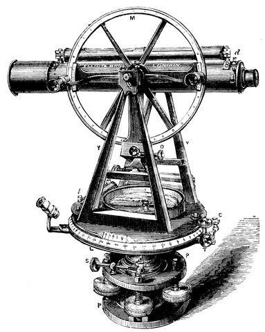
Fig. 132.—Theodolite.
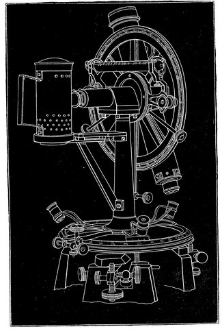
Fig. 133.—Portable Alt-azimuth.
If we refer again to Fig. 18, we see the method by which Tycho tried to get the two co-ordinates. On the horizontal circle there are the graduations for azimuth, or the measurement from the south along the horizon, and on the vertical quadrant are the graduations for altitude. Now let us turn to the modern equivalent of that instrument. Fig. 133 shows this in a portable form. The upper part of the instrument is, as one sees, nothing more than a transit circle exactly equivalent to the one 290described. We have a telescope carried on a horizontal axis, supported by a pillar; we have the reading microscopes, and the like; but the support of the horizontal axis, instead of being on the solid ground, as it is in the transit circle, rests on a movable horizontal circle, which is also read by microscopes arranged round it, so that all errors may be eliminated. With this instrument we can get the altitude of an object at any distance from the meridian, and at the same time measure its distance east and west of it. The arrangements designed by the Astronomer Royal for observations of the moon at Greenwich are more elaborate. In the Greenwich alt-azimuth, the telescope is swung on pivots between two piers, just as in the case of the transit, these piers being fixed to the horizontal circle.
The great advantage of this instrument is that the true place of a heavenly body can be determined whenever it is above the horizon; we have neither to wait for a transit over the meridian nor over the prime vertical. Nevertheless its use is not general in fixed observatories.
Reduce the dimensions of the horizontal circle and increase those of the vertical one, and we have the vertical circle designed by Ertel, and largely used in foreign observatories.
We have already gone somewhat in detail into the construction of the transit circle, which is almost the most important of modern astronomical instruments. We then referred to the alt-azimuth, in which, instead of dealing with those meridional measurements which we had touched upon in the case of the transit circle, we left, as it were, the meridian for other parts of the sphere and worked with other great circles, passing not through the pole of the heavens, but through the zenith.
We now pass to the “optick tube,” as used in the physical branch of astronomy, and we have first to trace the passage from the alt-azimuth to the Equatorial, as the most convenient mounting is called.
This equatorial gives the observer the power of finding any object at once, even in the day-time, if it be above the horizon; and, when the object is found, of keeping it stationary in the field of view. But although this form is the most convenient, it is not the one universally adopted, because it is expensive, and because, again, till within the last few years our opticians were not able to grapple with all its difficulties.
Hence it is that some of the instruments which have 294been most nobly occupied in investigations in physical astronomy have been mounted in a most simple manner, some of them being on an alt-azimuth mounting. Of these the most noteworthy example is supplied by the forty-feet instrument erected by Sir William Herschel at Slough.
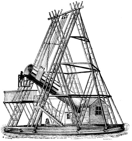
Fig. 134.—The 40-feet at Slough.
Lord Rosse’s six-feet reflector again is mounted in a different manner. It is not equatorially mounted; the tube, supported at the bottom on a pivot, is moved by manual power as desired between two high side walls, carrying the staging for observers, and so allowing the 295telescope a small motion in right ascension of about two hours. Our amateurs then may be forgiven for still adhering to the alt-azimuth mounting for mere star-gazing purposes.
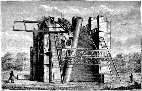
Fig. 135.—Lord Rosse’s 6-feet.
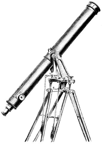
Fig. 136.—Refractor mounted on Alt-azimuth Tripod for ordinary Stargazing.
We must recollect that, with the alt-azimuth, we are 297able to measure the position of an object with reference to the horizon and meridian; but suppose we tip up the whole instrument from the base, so that, instead of having the axis of the instrument vertical, we incline it so as to make the axis, round which the instrument turns in azimuth, absolutely parallel to the earth’s axis.
Of course, if we were using it at the north pole or the south pole, the axis would be absolutely vertical, as when it is used as an alt-azimuth, or otherwise it would not be absolutely parallel to the axis of the earth. On the other hand, if we were using it at the equator, it would be essential that the axis should be horizontal, since to an observer at the equator the earth’s axis is perfectly horizontal; but, for a middle latitude like our own, we have to tip this axis about 51½° from the horizontal, so as to be in proper relationship with, i.e. parallel to, the earth’s axis. Having done this, we can, by turning the instrument round this axis, called the polar axis, keep a star visible in the field of view for any length of time we choose by exactly counteracting the rotation of the earth, without moving the telescope about its upper, or what was its horizontal, axis. The lower circle of the instrument will then be in the plane of the celestial equator, and the upper one, at right angles to it, will enable us to measure the distance from that plane, or the declination of an object, while the lower circle will tell us the distance of the object from the meridian in hours or degrees.
With the aid of good circles and good clocks, we can thus determine a star’s position. Fig. 137 shows an Equatorial Stand, one of the first kind of equatorials used by astronomers. We see at once the general arrangements 298of the instrument. In the first place, we have a horizontal base, D, and on it, and inclined to it, is a disc of metal, C; again on this disc lies another disc, A, B, which can revolve round on C, being held to it by a central stud, so that when A B is in the plane of the earth’s equator its axis points to the pole and is parallel to the axis of the earth. On the upper disc there are two supports for the axis of the telescope, E, which is at right angles to the polar axis and is called the declination axis of the telescope; round it the telescope has a motion in a direction from the pole to the equator.
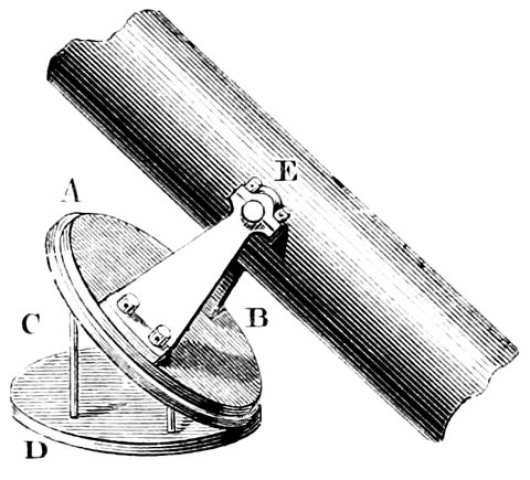
Fig. 137.—Simple Equatorial Mounting.
In the equatorial mounting, clockwork is introduced, and after the instrument has been pointed to any particular star or celestial body, the clock is clamped to the circle moving round the polar axis, and so made to drive it round in exactly the time the earth takes to make a rotation. By a clock is meant an instrument for giving motion, not with reference to time, but so arranged that, if it were possible to use it continuously, the motion would exactly bring the telescope round once in the twenty-four sidereal hours which 299are necessary for the successive transits of stars over the meridian.
There is an objection to the form of instrument given above,—the telescope cannot be pointed to any position near the pole, since the stand comes in the way. This is obviated in the various methods of mounting, which we shall now pass under review.
This is the form now almost universally adopted for refractors and reflectors under 20 inches aperture.
The polar axis has attached to it at right angles a socket through which the declination axis passes, and this axis carries the telescope at one end and a counterweight at the other. The polar axis lies wholly below the declination axis, and both are supported by a central pillar entirely of iron, or partly of stone and partly of iron.
By the courtesy of Messrs. Cooke and Sons, Mr. Howard Grubb, and Mr. Browning, we are enabled to give examples of the various forms of this mounting now in use in this country for instruments of less than 20 inches aperture.
In Fig. 138, we have the type form of Equatorial Refractor introduced some 30 years ago by the late Mr. Thomas Cooke. The telescope is represented parallel to the polar axis, which is inclosed in the casing supported by the central pillar, and carries one large right ascension circle above and another smaller one below, the former being read by microscopes attached to the casing.
The socket or tube carrying the declination axis is connected with the top of the polar axis. To this the 300declination circle is fixed, while an inner axis fixed to the telescope carries the verniers.
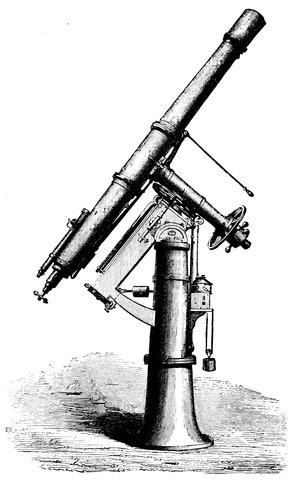
Fig. 138.—Cooke’s form for Refractors.
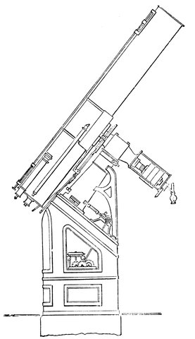
Fig. 139.—Mr. Grubb’s form applied to a Cassegrain Reflector.
The clock is seen to the north of the pillar. While this is driving the telescope, rods coming down to the eyepiece enable the observer to make any small alterations in right ascension or declination; indeed in all modern instruments everything except winding the clock 302is done at the eyepiece, so that the observer when fairly at work is not disturbed. The lamp to illuminate the micrometer wires is shown near the finder. The friction rollers, which take nearly all the weight off the surfaces of the polar axis, are connected with the compound levers shown above the casing of the polar axis.
In Fig. 139 we have Mr. Grubb’s revision of the German form. The pillar is composite, and the support of the upper part of the polar axis is not so direct as in the mounting which has just been referred to. There are, however, several interesting modifications to which attention may be drawn. The lamp is placed at the end of the hollow polar axis, and supplies light not only for the micrometer wires, but for reading the circles; the central cavity of the lower support is utilised for the clock, which works on part of a circle, instead of a complete one, as in the instrument already described.
In the case of Newtonian reflectors the observer requires to do his work at the upper end of the tube; this therefore should be as near the ground as possible. This is accomplished by reducing the support to a minimum. Figs. 140 and 141 show two forms of this mounting, designed by Mr. Grubb and Mr. Browning.
The two largest and most perfectly mounted refractors on the German form at present in existence are those at Gateshead and Washington, U.S. The former belongs to Mr. Newall, a gentleman who, connected with those who were among the first to recognise the genius of our great English optician, Cooke, did not hesitate to risk thousands of pounds in one great experiment, the success of which will have a most important bearing upon the astronomy of the future.
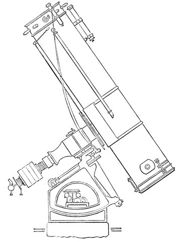
Fig. 140.—Grubb’s form for Newtonians.
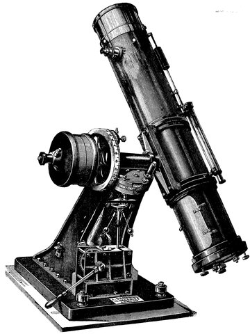
Fig. 141.—Browning’s mounting for Newtonians.
In the year 1860 the largest refractors which had been turned out of the Optical Institute at Munich under the control, first, of the great Fraunhofer, and afterwards of Merz, were those of 177 square inches area at Poulkowa 305and Cambridge (U.S.). Our own Cooke, who was rapidly bringing back some of the old prestige of Dollond and Tulley’s time to England—a prestige which was lost to us by the unwise meddling of our excise laws and the duty on glass,[16] which prevented experiments in glass-making—had completed a 9⅓ inch for Mr. Fletcher and a 10 inch for Mr. Barclay; while in America Alvan Clarke had gone from strength to strength till he had completed a refractor of 18½ inches for Chicago. The areas of these objectives are 67, 78·5, and 268 inches respectively.
Those who saw the great Exhibition of 1862 may have observed near the Armstrong Gun trophy two circular blocks of glass some 26 inches in diameter and about two inches thick standing on their edges. These were two of the much-prized “discs” of optical glass manufactured by Messrs. Chance of Birmingham.
At the close of the Exhibition they were purchased by Mr. Newall, and transferred to the workshops of Messrs. Cooke and Sons at York.
The glass was examined and found perfect. In time the object-glass was polished and tested, and the world was in possession of an astronomical instrument of nearly twice the power of the 18½ inch Chicago instrument—485 inches area to 268.
Such an achievement marks an epoch in telescopic astronomy, and the skill of Mr. Cooke and the munificence of Mr. Newall will long be remembered.
The general design and appearance of this monster 306among telescopes will be gathered from the general view given in the frontispiece, for which we are indebted to Mr. Newall. It is the same as that of the well-known Cooke equatorials; but the extraordinary size of all the parts has necessitated the special arrangement of most of them.
The length of the tube, including dew-cap and eye-end, is 32 feet, and it is of a cigar shape, the diameter at the object-end being 29 inches, at the centre of the tube 34 inches, and at the eye-end 22 inches. The cast-iron pillar supporting the whole is 19 feet in height from the ground to the centre of the declination axis, when horizontal; and the base of it is 5 feet 9 inches in diameter. The trough for the polar axis alone weighs 14 cwt., the weight of the whole instrument being nearly 6 tons.
The tube is constructed of steel plates riveted together, and is made in five lengths screwed together with bolts. The flanges were turned in a lathe, so as to be parallel to each other. It weighs only 13 cwt., and is remarkably rigid.
Inside the outer tube are five other tubes of zinc, increasing in diameter from the eye to the object-end; the wide end of each zinc tube overlapping the narrow end of the following tube, and leaving an annular space of about an inch in width round the end of each for the purpose of ventilating the tube, and preventing, as much as possible, all interference by currents of warm air with the cone of rays. The zinc tubes are also made to act as diaphragms.
The two glasses forming the object-glass weigh 144 lb., and the brass cell weighs 80 lb. The object-glass has an aperture of nearly 25 inches, or 485 inches area, and in 307order as much as possible to avoid flexure from unequal pressure on the cell, it is made to rest upon three fixed points in its cell, and between each of these are arranged three levers and counterpoises round a counter-cell, which act through the cell direct on to the glass, so that its weight in all positions is equally distributed among the twelve points of support, with a slight excess upon the three fixed ones. The focal length of the lens is 29 feet.
Attached to the eye-end of the tube are two finders, each of 12·5 inches area; they are fixed above and below the eye-end of the main tube, so that one may be readily accessible in all positions of the instrument. It is also supplied with a telescope having an object-glass of 33 inches area. This is fixed between the two finders, and is for the purpose of assisting in the observations of comets and other objects for which the large instrument is not so suitable. This assistant telescope is provided with a rough position circle and micrometer eyepieces.
Two reading microscopes for the declination circle are brought down to the eye-end of the main tube; the circle—38 inches in diameter—is divided on its face and edge, and read by means of the microscopes and prisms.
The slow motions in declination and R. A. are given by means of tangent screws, carrying grooved pulleys, over which pass endless cords brought to the eye-end. The declination clamping handle is also at the eye-end.
The clock for driving this monster telescope is fixed to the lower part of the pillar, and is of comparatively small proportions, the instrument being so nicely counterpoised that a very slight power is required to be exerted by the clock, through the tangent screw, on the driving-wheel 308(seven feet in diameter), in order to give the necessary equatorial motion.
The declination axis is of peculiar construction, necessitated by the weight of the tubes and their fittings, and corresponding counterpoises on the other end, tending to cause flexure of the axis. This difficulty is entirely overcome by making the axis hollow, and passing a strong iron lever through it having its fulcrum immediately over the bearing of the axis near the main tube, and acting upon a strong iron plate rigidly fixed as near the centre of the tube as possible, clear of the cone of rays. This lever, taking nearly the whole weight of the tubes, &c., off the axis, frees it from all liability to bend.
The weight of the polar axis on its upper bearing is relieved by anti-friction rollers and weighted levers; the lower end of the axis is conical, and there is a corresponding conical surface on the lower end of the trough; between these two surfaces are three conical rollers carried by a loose or “live” ring, which adjust themselves to equalize the pressure.
The hour-circle on the bottom of the polar axis is 26 inches in diameter, and is divided on the edge, and read roughly from the floor by means of a small diagonal telescope attached to the pillar; a rough motion in R. A. by hand is also arranged for, by a system of cogwheels, moved by a grooved wheel and endless cord at the lower end of the polar axis, so as to enable the observer to set the instrument roughly in R. A. by the aid of the diagonal telescope. It is also divided on its face, and read by means of microscopes. The declination and hour-circle will probably be illuminated by means of Geissler tubes, and the dark and bright field illuminations for the micrometers will be effected by the same means.
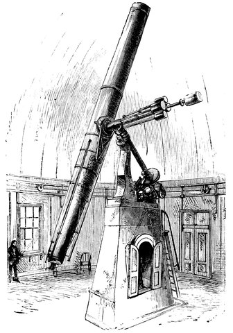
Fig. 142.—The Washington Great Equatorial.
So soon as the success of the Newall experiment was put beyond all question by Cooke, Commodore B. F. Sands, the superintendent of the U.S. Naval Observatory, sent a deputation, consisting of Professors S. Newcomb, Asaph Hall, and Mr. Harkness, accompanied by Mr. Alvan Clarke, to examine and report upon the Newall telescope, and the result was that they commissioned Alvan Clarke to construct a large telescope for that country.
310In the Washington telescope the aperture of the object-glass is 26 inches—that is, one inch larger than the English type-instrument. The general arrangements are shown in the accompanying woodcut.
It will be seen that the mounting is much lighter than in the English instrument, and a composite pillar gives place for the clock in the central cavity.
In the English mounting the telescope, like a transit instrument, has on each side a pivot, and these pivots rest on a frame somewhat larger than the telescope, pointing to the pole and supported by two pivots, one at the bottom resting on bearings near the ground, and the other carried by a higher pillar clear of the observer’s chair. The motions of the telescope are similar to those given by the German mounting in all essentials; the Greenwich equatorial is mounted in this manner. It is carried in a large cylindrical frame, supported at both ends by two pillars—above by a strong iron pillar, while the other end rests on a firm stone pillar, going right to the earth, independently of the flooring. This mounting, though preferred for the large instrument at Greenwich, has been discarded generally, as the long polar axis is necessarily a serious element of weakness; the telescope is supported on its weakest part, and it is liable to great changes from contraction and expansion of the frame.
It is now getting more usual to mount Newtonians of large dimensions equatorially, in spite of the immense weight to be carried. One of the first methods was to 311use a polar axis in the same manner as for a refractor, only that it bifurcated at the top, forming there a fork, and between this fork the telescope is swung, after the same manner as a transit. This method of mounting was adopted by M. Foucault in the case of his first large silvered-glass reflector. The height of the bifurcation is dependent on the distance between the centre of gravity of the tube and the speculum, and if we use an extremely light tube, or if,—as it is the fashion to abolish them now altogether for reflectors,—we use a skeleton tube of iron lattice work, this bifurcation of the polar axis need not be of any great length. The polar axis being entirely below the telescope and being driven by the clock, we have a perfect method of mounting a speculum of any weight we please. This arrangement was first suggested and carried into effect by Mr. Lassell for his four-foot Newtonian, which was mounted at Malta. The polar axis was a heavy cone-shaped casting resting on its point below, and moving on its largest diameter just below the base of the fork. Lord Rosse has recently much improved upon the original idea.
As the observer must be at the mouth of the tube, he is in a very bad position as far as comfort goes, especially as the eye-end changes its position rapidly in consequence of the great length of the tube from its centre of gravity outwards. The platform on which he stands is raised on supports, extending from the floor and going up to the opening through which the telescope points to the heavens, and the whole platform is sometimes fixed to the dome of the observatory, so that it travels round with it.
With Mr. Lassell’s four-foot the observer stood in a 312gigantic reading box, about thirty feet high, with openings in it at different elevations. This structure was supported on a circular platform movable on rails round the base of the mounting. Almost continual variations, both of the observing height and of the circular platform, were necessary, as the distance from the centre of motion of the tube and the eyepiece was no less than 34 feet.
In Lord Rosse’s recent adaptation of this form the observer is placed in a swinging basket, at the end of an arm almost as long as the telescope tube. He is here counterpoised, and moves round a railway which surrounds the mounting at the height of the tip of the fork.
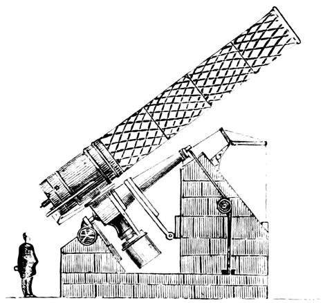
Fig. 143.—General view of the Melbourne Reflector.
There is still another form of mounting which promises to be largely used for reflectors in the future, whether the tube be lightened by its being constructed of only a framework of iron or not. This mounting is neither German nor English, but in part imitates both of these methods: hence I give it the name of Composite. There is a short polar axis supported at both ends.
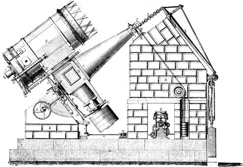
Fig. 144.—The mounting of the Melbourne Telescope. C, polar axis (cube 1 yard square, cone 8 feet long); D, Clock sector; U, Counterpoise weights (2¼ tons).
314Within the last few years two large reflectors have been erected, equatorially mounted in this composite manner—the great Melbourne Equatorial, constructed by Mr. Grubb, and the new Paris Equatorial, constructed by Mr. Eichens.
Of the former, Fig. 143 gives a general view, showing how the construction of this instrument differs from other equatorials which we have seen. Fig. 144 shows the mounting in more detail. C is the polar axis, T P is the declination axis, and T the small portion of the tube of the telescope, the remainder of the tube being represented by delicate lattice work, which is as light as possible, and used merely for supporting the reflector, by means of which the light is thrown back again, according to the suggestion of Cassegrain, and comes through the hole in the centre of the speculum into the eyepiece, which is seen at y, so that the observer stands at the bottom of the telescope in exactly the same way as if he were using a refractor.
In this enormous instrument, the tube and speculum of which alone weigh nearly three tons, the system of counterpoises is so perfect that we describe the method adopted in order to give an idea of the general arrangement of the bearing and anti-frictional apparatus. The series of weights hanging behind the support of the upper end of the polar axis are intended to take a great part of the weight of that axis off the lower support; beside which there are friction-rollers pressed upwards against the axis by the weights inside the support.
All the bearings are constructed on the same principle as the Y bearings of a theodolite—that is, the pivots rest on two small portions of their arc, 90° or 100° apart.
If allowed to rest on these bearings without some 315anti-frictional apparatus, the force required to move such an instrument would render it simply unmanageable and destroy the bearings.
The plan adopted by Mr. Grubb is to allow the
axis to rest in its bearings with just a sufficient portion
of its weight to insure perfect contact, and to support
the remainder by some anti-frictional apparatus. Generally
1
50 to 1
100 of the weight is quite sufficient to allow
the axis to take its bearing, and the remainder 49
50 to 99
100
can thus be supported on friction rollers, and reduced
to any desired extent, without injuring in the slightest
degree the perfection of steadiness obtained by the use
of the Y’s. This is the plan used in the bearings of the
polar axis, and the result is that the instrument can be
turned round this axis by a force of 5 pounds at a leverage
of 20 feet. The bearings of the declination axis are
supported on virtually the same principle; but the details
of that construction are necessarily much more complicated,
on account of the variability of direction of the
resolved forces with respect to the axis.
We may now turn to the four-foot silver-on-glass Newtonian now in course of completion at the Paris Observatory.
The illustration which we give represents the telescope in a position for observation. The wheeled hut under which it usually stands, a sort of waggon seven metres high by nine long and five broad, is pushed back towards the north along double rails. The observing staircase has been fitted to a second system of rails, which permits it to circulate all round the foot of the telescope, at the same time that it can turn upon itself, for the purpose of placing the observer, standing either on the steps or on the upper balcony, within reach of 316the eyepiece. This eyepiece itself may be turned round the end of the telescope into whatever position is most easily accessible to the observer.
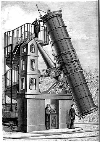
Fig. 145.—Great Silver-on-Glass Reflector at the Paris Observatory.
317The tube of the telescope, 7·30 metres in length, consists of a central cylinder, to the extremities of which are fastened two tubes three metres long, consisting of four rings of wrought-iron holding together twelve longitudinal bars also of iron. The whole is lined with small sheets of steel plate. The total weight is about 2,400 kilogrammes. At the lower extremity is fixed the cell which holds the mirror; at the other end a circle, movable on the open mouth of the telescope, carries at its centre a plane mirror, which throws to the side the cone of rays reflected by the great mirror.
The weight of the mirror in its barrel is about 800 kilogrammes; the eyepiece and its accessories have the same weight.[17]
It will be quite clear from what has been said that the manipulation of these large telescopes at present entails much manual and even bodily labour, and when we come in future to consider the winding of the clock, the turning of the dome, and the adjustment of the observing chair, it will be seen that the labour is enormous. To save this, in all the best instruments everything is brought to the eye-end of the telescope, movements both in right ascension and declination, reading of circles, and adjustment of illumination. Mr. Grubb has suggested that everything should be brought to this point, and that, by the employment of hydraulic power, “the observer, without moving from his chair, might, by simply pressing one or other of a few electrical buttons, cause the telescope to move round in right ascension, or declination, 318the dome to revolve, the shutters to open, and the clock to be wound.” He very properly adds, “This is no mere Utopian idea. Such things are done, and in common use in many of our great engineering establishments, and it is only in the application that there would be any difficulty encountered.”
In a previous chapter it was stated that in all large telescopes used for the astronomy of position, whether a transit circle or the alt-azimuth, what we wanted to do was to note the transit of the star across the field—the transit due to the motion of the earth; but that when we deal with other phenomena, such, for instance, as those a large equatorial is capable of bringing before us, we no longer want these objects to traverse the field, we want to keep them, if possible, absolutely immovable in the field of view of the eyepiece, so that we may examine them and measure them, and do what we please with them.
Hence it was that we found driving clocks applied to equatorials; and our description would not be complete did we fail to explain the general principles of their construction. They are instruments for counteracting the motion of the earth by supplying an exactly equal motion to the tube of the telescope in an opposite direction.
Without such a clock we may get an image of the object we wish to examine; but before we should be able to do anything with it, either in the way of measurement or observation, it would have gone from us. A glimpse of a planet or star with a large telescope 319will give a general notion of the extreme difficulty which any observer would have to deal with if he wanted to observe any heavenly body without a driving clock.
We can easily see at once that it would not do to have an ordinary clock regulated by a pendulum for driving the telescope, it would be driven by fits and starts, which would make the object viewed jump in the field at each tick of the pendulum. The most simple clock is therefore one in which the conical pendulum is used in the form of the governor of a steam-engine, so that when the balls A A, Fig. 146, fly up by reason of the clock driving too fast, they rub against a ring, B, or something else that reduces their velocity.
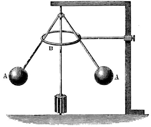
Fig. 146.—Clock Governor.
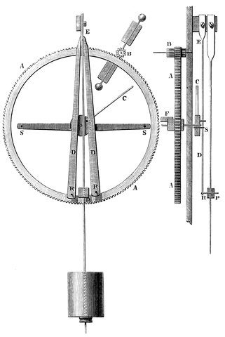
Fig. 147.—Bond’s Spring Governor.
There is another form made by Alvan Clarke, in which a pendulum regulates the clock, but not quite in the ordinary way. The drawing will perhaps make it clear: A A, Fig. 147, is one of the wheels of the clock-train driving a small weighted fan, B, which is regulated so as to allow the clock to drive a little too fast. Now let us see how the pendulum regulates it. On the axis of A A is placed an arm, C, which is of such a length that it catches against the studs S S, and is stopped until the 321pendulum, P, swings up against one of the studs, R, which moves the piece D, like a pendulum about its spring at E, until the stud, S, is sufficiently removed to let the arm, C, pass, so that the clock is under perfect control. If, however, the arm C were fixed rigidly to the axis of the wheel A A, there would be a jerk every time C touched one of the studs. The wheel is therefore attached to the axis through the medium of a spring, F, so that when the arm is stopped the wheel goes on, but has its velocity retarded by the pressure of the spring. The pendulum is kept going in the following manner:—There is a pin fixed to the axis on the same side of the centre as C, which, as the arm approaches either stud S, raises the piece D, but not sufficiently to liberate the arm; the pendulum has then only a very little work to do to raise D and disengage the arm, C; but as soon as it is free it starts off with a jerk, due to the tension of the spring on the axis, and leaves D by means of its stud, R, to exert its full force on the pendulum and accelerate its return stroke, so that the pendulum is kept in motion by the regulating arrangement itself.
The late Mr. Cooke of York constructed a very accurately-going driving clock. This differs in important particulars from Bond’s form, though the control of the pendulum is retained.
The following extracts from a description of it will show the principal points in its construction:—
The regulator adopted is the vibrating pendulum, because amongst the means at the mechanician’s command for obtaining perfect time-keeping there is none other by which the same degree of accuracy can be obtained. The difficulty in this construction is the conversion of the jerking or intermittent motion produced by such pendulums into a uniform rotatory 322motion which can be available with little or no disturbing influence on the pendulum itself, when the machine is subject to varying frictions and forces to be overcome in driving large equatorials.
The pendulum is a half-second one, with a heavy bob, adjusted by sliding the suspension through a fixed slit. It is drawn up and let down by a lever and screw, the acting length of the pendulum being thus regulated.
The arrangement of the wheels represents something like the letter U. At the upper end of one branch is the scape-wheel. At the upper end of the other branch is an air-fan. The large driving-wheel and barrel are situated at the bottom or bend. All the wheels are geared together in one continuous train, which consists of eight wheels and as many pinions. The scape-wheel and the two following wheels have an intermittent motion; all the others have a continuous and uniform one.
The change from one motion to the other is made at the third wheel, which, instead of having its pivot at the end of the arbor where the wheel is fixed—fixed to the frame like the others—is suspended from above by a long arm having a small motion on a pin fixed to the frame; the pivot at the other end of the arbor is fixed to the frame as the others are, but its bole and its pivot are arranged so as to permit a very small horizontal angular motion round them, as a centre, without interfering with the action of the gearing of the wheel itself.
If the weight is applied to the clock, and the pendulum is made to vibrate, the moment it begins to move, the scape-wheel moves its quantity for a beat; the remontoire wheel, by the very small force outwardly caused by the reaction of the break-spring, relaxes its pressure against a friction-wheel, and sets at liberty the train of the clock.
The spring is now driven back to the break-wheel, but before it can produce more than the necessary friction to keep the train in uniform motion, another beat of the clock again releases it. The repetition of these actions produces a series of impulses on the break-wheel of such a force and nature as to keep the train freely governed by the pendulum.
The uniform rotatory motion obtained by this clock as far as experiments can be made by applying widely different weights, 323and comparing the times with a chronometer, is perfectly satisfactory.
A clock constructed on the same principle, connected, and giving motion to a cylinder, will, it is presumed, make an excellent chronograph.
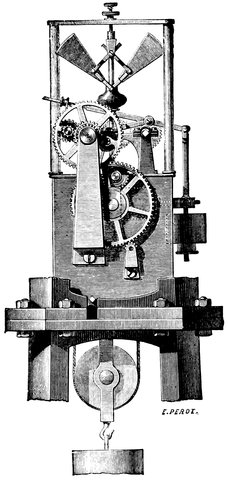
Fig. 148.—Foucault’s governor.
The form of governor most usually employed will be seen in figures previously given. The governor raises a plate and thus becomes a frictional governor, by which 324all overplus of power is used up in frictions, or by that doubling the driving power no, or only a small, difference should be brought about in the rate.
Other forms of driving clocks or governors invented by Foucault and Yvon Villarceau are now being largely employed. In them the rapid motion of a fan and other devices are introduced.
A driving clock adjusted to sidereal time requires adjustments for observations of the sun and moon. This (as at z in Fig. 144) is sometimes done once for all by differential gearing thrown into action by levers when required.
Mr. Grubb has lately made a notable improvement upon the usual form by controlling the motion of the governor by a sidereal clock and an electric current.
There are various methods of attaching the clock to the polar axis. One is to make the clock turn a tangent screw, gearing into a screw-wheel on the axis of the telescope, which can be thrown in and out of gear for moving the telescope rapidly in right ascension. Another method is to have a segment of a circle on the polar axis which can be clamped or unclamped at pleasure by means of a screw attached to it. A strip of metal is attached to each end of the segment and is wound round a drum turned by the clock, so that the two are geared together just as wheels are geared by an endless strap passing round them. This arrangement gives a remarkably even motion to the telescope. When the strap is wound up to the end of the segment, which is done in about two or three hours’ work, the drum is thrown out of gear and the arc pushed back to its starting-place again.
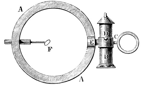
Fig. 149.—Illuminating lamp for equatorial.
In the description of the transit circle we saw how the Astronomer-Royal had contrived to throw light into the axis of the telescope, so that the wires were either rendered visible in a bright field, or, the field being kept dark, the wires were visible as bright lines in a dark field. That is the difference between a bright field, and a dark field of illumination. Now a bright field of illumination in the case of equatorials is managed by an arrangement as follows.—A A, Fig. 149, is a section of the tube of the telescope. Near the eyepiece is a small lamp, D, swung on pins on either side which rest on a circular piece of brass swinging on a pin at C, and a short piece of tube at E, through which the light passes into the telescope and falls on a small diagonal reflector, F. This reflects the rays downwards into the eyepiece. When the telescope is moved into any position the lamp swings like a mariner’s compass on its gimbals, and still throws its light into the tube, and the light mixes up with that coming from the star, but spreads all over the field of 326view instead of coming to a point, so that the star is seen on a bright field, and the wires as black lines. Now if the star which is observed is a very faint one, we defeat our own object, for the light coming from the lamp puts out the faint star.
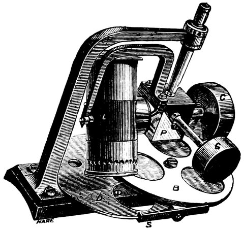
Fig. 150.—Cooke’s illuminating lamp.
We have seen how the illumination of the wires, instead of the field, is carried out in the Greenwich transit. The same method can be adopted in the case of equatorials, the light from the diagonal reflector being thrown on other diagonal reflectors or prisms on either side the wires in the micrometer so as to illuminate them. Messrs. Cooke and Sons have devised a lamp of very great ingenuity, Fig. 150. It is a lamp which does for the equatorial, in any position, exactly what the fixed lamp does for the transit circle. It is impossible to put it out of order by moving the telescope. There is a prism at P reflecting the light into the telescope tube, and at whatever different angle of inclination, or whatever may be the size of the telescope on which this lamp is placed, it is obvious that the lamp never ceases to throw its light into the reflector inside the telescope; and any 327amount of light, or any colour of light required can be obtained by turning the disc containing glass of different colours or the other having differently sized apertures, in order to admit more or less light, or give the light any colour.
In both these arrangements the lamp is hung on the side of the telescope, while Mr. Grubb prefers to hang it at the end of the declination axis, as shown in Figs. 139 and 140.
The function of the lamp then is to illuminate the wires of the micrometer eyepiece, of which more presently; but Mr. George Bidder places the micrometer itself outside the tube of the telescope, the light of a lamp being thrown on the wires.
This is done as follows:—On the same side of the wires as the lamp is a convex lens and reflector so arranged that the rays from the wires are reflected through a hole in the tube, and again down the tube to the eyepiece, where the images of the wires are brought to a focus at the same place as the stars to be measured, so that any eyepiece can be used. The wires show as bright lines in the field, and they are worked about in the field just as real wires might be by moving the wires outside the tube. A sheet of metal can be moved in front of the distance-wires so as to obstruct the light from them at any part of their length, and their bright images appear then abruptly to terminate in the field of view, so that faint stars can be brought up to the terminations of the wires and be measured without being overcome by bright lines.
16. It is not too much to say that the duty on glass entirely stifled, if indeed it did not kill, the optical art in England. We were so dependent for many years upon France and Germany for our telescopes, that the largest object-glasses at Greenwich, Oxford, and Cambridge are all of foreign make.
17. These details are given from the Forces of Nature (Macmillan).
As the equatorial is par excellence the amateur’s instrument, and as in setting up an equatorial it is important that the several adjustments should be correctly made, they are here dwelt upon as briefly as possible. They are six in number.
1. The inclination of the polar axis must be the same as that of the pole of the heavens.
2. The declination circle must read 0° when the telescope is at right angles to the polar axis.
3. The polar axis must be placed in the meridian.
4. The optic axis of the telescope, or line of collimation must be at right angles to the declination axis, so that it describes a great circle on moving about that axis.
5. The declination axis must be at right angles to the polar axis, in order that the telescope shall describe true meridians about that axis.
6. The hour circle must read 0h. 0m. 0sec. when the telescope is in the meridian.
When these are correctly made the line of collimation will, on being turned about the declination axis, describe great circles through the pole, or meridians, and when 329moved about the polar axis, true parallels of declination; and the circles will give the true readings of the apparent declination, and hour angles from the meridian.
To make these adjustments, the telescope is set up by means of a compass and protractor, or otherwise in an approximately correct position, the declination circle put so as to read nearly 90° when the telescope points to the pole, and the hour circle reading 0h. 0m. 0sec. when the telescope is pointing south.
First, then, to find the error in altitude of the polar axis.
Take any star from the Nautical Almanac of known declination on or near the meridian, and put an eyepiece with cross wires in it in the telescope, and bring the star to the centre of the field as shown by the wires. Then read the declination circle, note the reading down and correct it for atmospheric refraction, according to the altitude[18] of the star by the table given in the Nautical Almanac, turn the telescope on the polar axis round half a circle so that the telescope comes on the other side of the pier. The telescope is then moved on its declination axis until the same star is brought to the centre of the field, and the circle read as before and corrected. The mean of the two readings is then found, and this is the declination of the star as measured from the equator of the instrument, and its difference from the true declination given by the almanac is the error 330of the instrumental equator and of course, also of the pole at right angles to it.
It is obvious that if the declination circle were already adjusted to zero, when the telescope was pointing to the equator of the instrument, one observation of declination would determine the error in question; and it is to eliminate the index error of the circle, as it is called, that the two observations are taken in such a manner that the index error increases one reading just as much as it decreases the other, so that the mean is the true instrumental declination.
Index Error.—From what has just been stated it follows that half the difference of the two readings is the index error, which can be at once corrected by the screws moving the vernier, giving correction No. 2.
To correct the error in altitude of the pole, the circle is then set to the declination of the star given by the almanac, corrected for refraction, and the telescope brought above or below the star as the error may be, and the polar axis carrying the telescope is moved by the setting screws, until the star is in the centre of the field.
3rd Adjustment.—A single observation of any known star, about 6 hours to the east or west will give the error of the polar axis east and west, the difference between the observed and true declination being this error, and it can be corrected in the same manner as the last. These observations should be repeated, and stars in different parts of the heavens observed, in order to eliminate errors of division of the circle until the necessary accuracy is obtained.
331For example:
| Observed dec. of Capella | 43° | 50´ | 30˝ | Telescope west. | |||
| 47° | 0´ | 0˝ | Telescope east. | ||||
| ——— | ——— | ——— | |||||
| 2) | 90° | 50´ | 30˝ | ||||
| ——— | ——— | ——— | |||||
| 45° | 25´ | 15˝ | 47° | 0´ | 0˝ | ||
| Error due to refraction | 0° | 0´ | 7˝ | 43° | 50´ | 30˝ | |
| ——— | ——— | ——— | ——— | ——— | ——— | ||
| Instrumental declination | 45° | 25´ | 8˝ | 2) | 3° | 9´ | 30˝ |
| True declination | 45° | 52´ | 0˝ | ——— | ——— | ——— | |
| ——— | ——— | ——— | Index error | 1° | 34´ | 45˝ | |
| 26´ | 52˝ |
This indicates that the pole of the instrument is pointing below the true pole, and index error 1° 34´ 45˝.
| Observed declination of Pollux 6h. west | 28° | 19´ | 18˝ |
| Refraction | 0° | 0´ | 46˝ |
| ——— | ——— | ——— | |
| 28° | 18´ | 3˝ | |
| True declination | 28° | 20´ | 10˝ |
| ——— | ——— | ——— | |
| 0° | 1´ | 38˝ |
This shows the pole to be 1´ 38˝ east of true pole.
4th Adjustment.—For the estimation and correction of the third error, that of collimation, an equatorial star is brought to the centre of the field of the telescope, the time by a clock noted, and the hour circle read. The polar axis is then turned through half a circle, and the star observed with the telescope on the opposite side (say the west) of the pier, the time noted, and the hour circle read. Subtract the first reading from the second (plus twenty-four hours if necessary) and subtract the time elapsed between them, and the result should be exactly twelve hours, and half the difference between it and twelve hours is the error in question. If it is more than twelve hours the angle between the object end of 332the telescope and the declination axis is acute, and if less then it is obtuse. This error can then be corrected by the proper screws. A little consideration will show, that if the angle between the object end of the telescope and the declination axis be acute, and the telescope is on the east side of the pier, and pointing to a star, say on the meridian, the hour circle will not read so much as it would do if the line perpendicular to the declination axis were pointing to the meridian. When the telescope is on the wrest side of the pier, the circle will read higher for the same reason, and therefore the difference between the angle through which the hour circle is moved and 180° is equal to double the angle between the line perpendicular to the declination axis and the collimation axis of the telescope; allowance being made for the star’s motion.
For example γ Virginis, Dec. 0° 46´·5.
| Time by clock. | Hour circle reading. | |||||
|---|---|---|---|---|---|---|
| 11h. | 23m. | 52s. | 11h. | 55m. | 30s. | Telescope east. |
| 11h. | 31m. | 55s. | 24h. | 8m. | 24s. | Telescope west. |
| ———— | ———— | ———— | ———— | ———— | —————— | |
| 8m. | 3s. | 12h. | 12m. | 54s. | ||
| 8m. | 3s. | |||||
| ———— | —————— | |||||
| 2) | 4m. | 51s. | ||||
| ———— | —————— | |||||
| Collimation error at dec. 46´·5 | 2m. | 25·5s. | ||||
| angle between object glass and declination axis acute. | ||||||
If this error is not corrected, it must be added when the telescope is on the east side of the pier, and subtracted when on the west.[19]
5th Adjustment.—Place a striding level on the pivots 333of the declination axis and bring the bubble to zero by turning the polar axis; read off the hour circle and note it; then reverse the declination axis east and west and replace the level; bring the bubble to zero and again read the circle. The readings should show the axis to be turned through half a circle, and the difference shows the error.
If the second reading minus the first be more than half a circle or 12 hours, it shows that the pivot at the east at the first observation is too high, and therefore in bringing the declination axis level, the first reading of the hour circle is diminished from its proper amount and increased on the axis being reversed.
To adjust the error, find half the difference of circle readings and apply it, with the proper sign, to each of the two circle readings, which will then differ by exactly twelve hours; bring the circles to read one of the corrected readings and alter the declination axis until the bubble of the level comes to zero. If the pivots of the declination axis are not exposed, so that the level can be applied, the following method must be adopted:—Fasten a small level on any part of the declination axis or its belongings, say on the top of the counterpoise weight; bring the axis apparently horizontal and the bubble to zero; turn the telescope on the declination axis, so that by the turning of the counterpoise the level comes below it; if then the bubble is at zero, the axis of the level is parallel to the declination axis, and both are horizontal, and if not it is clear that neither of these conditions holds; therefore bring the bubble to zero by the two motions of the level with reference to the counterpoise and the motion of the declination axis on the polar axis, so that the error is equally corrected between them; repeat the proceeding 334until the level is parallel with the axis, when it will show when the axis is horizontal as well as the striding level.
For example:—
| Hour circle reading when | } | 11h. | 57m. | 57s. | Telescope east. |
| declination axis is horizontal. | } | 23h. | 59m. | 47s. | Telescope west. |
| ———— | ———— | ———— | |||
| 12h. | 1m. | 50s. | |||
| Error | 0h. | 1m. | 50s. |
Or this error can be found and corrected without a level by taking two observations of a star of large declination in the same manner as in estimating the collimation error, for example:—
| η Ursæ Majoris. | |||||||
| Time by clock. | Hour circle reading. | ||||||
|---|---|---|---|---|---|---|---|
| 12h. | 8m. | 57s. | 0h. | 28m. | 44s. | Telescope east. | |
| 12h. | 18m. | 53s. | 12h. | 46m. | 42s. | Telescope west. | |
| ———— | ———— | ———— | ———— | ———— | ———— | ||
| 9m. | 56s. | 12h. | 17m. | 58s. | |||
| 9m. | 56s. | ||||||
| ———— | ———— | ||||||
| 2) | 8m. | 2s. | |||||
| ———— | ———— | ||||||
| Error of hour circle due to error of inclination of axes[20] | 4m. | 1s. | |||||
6th Adjustment.—Bring the declination axis to a horizontal position with a level and set the hour circle to zero, or obtain the sidereal time from the nearest observatory, or again find it from the solar time by the tables, and correct it for the longitude of the place (subtracting 335the longitude reduced to time when the place is west and adding when east of the time-giving observatory) and set a clock or watch to it. Take the time of transit of a known star near the meridian and then the sidereal time by the clock at transit minus the right ascension of the star will give the hour angle past the meridian, and its difference from the circle reading is the index error, which is easily corrected by the vernier. If the star is east of the meridian the time must be subtracted from the right ascension to give the circle reading.
In the above examples we have assumed, for the sake of better illustration, that the hour circle is divided into twenty-four hours, but more usually they are divided into two halves of twelve hours each. A movement through half a circle, therefore, brings the hour circle to the same reading again instead of producing a difference of twelve hours, as in the above example.
When the equatorial is once properly in adjustment, not only can the co-ordinates of a celestial body be observed with accuracy when the time is known, but a planet or other body can easily be found in the day-time. The object is found by the two circles—the declination circle and the hour or right-ascension circle. The declination of the required object being given, the telescope is set by the circle to the proper angle with the equator. The R.A. of the object is then subtracted from the sidereal time, or that time plus twenty-four hours, which will give the distance of the object from the meridian, and to this distance the hour-circle is set. The object should then be in the field of the telescope, or at least in that of the finder. We subtract the star’s R.A. from the sidereal time because the clock shows the 336time since the first point of Aries passed the meridian, and the star passes the meridian later by just its R.A., so that if the time is 2h., or the first point of Aries has passed 2h. ago, a star of 1h. R.A., or transiting 1h. after that point, will have passed the meridian 2h. - 1h. = 1h. ago; so if we set the telescope 1h. west of the meridian we shall find the star. The moment the object is found the telescope is clamped in declination, and the clock thrown into gear, so that the star may be followed and observed for any length of time.
18. The altitude of the star in this case is its declination plus the co-latitude of the place, but this only applies when the star is on the meridian. When the altitude of a star in another situation is required, it is found sufficiently accurately by means of a globe. A sextant, if at hand, will of course give it at once.
19. Since the velocity of the star varies as the cosine of the declination, the error of collimation at the equator = 2m. 25·5s. cos. 0° 45´·5 = 2m. 25·08s.; and for non-equatorial stars, 2m. 25·08s. sec. dec.
20. This error varies as the tangent of the declination, and therefore to find the constant for the instrument, in case the parts do not admit of easy adjustment, we divide 4m. 1s. by 1·18 the tan. of Dec. of η Ursæ Majoris, giving 3 min. 28 sec.
We have now considered the mounting and adjustment of the equatorial, be it reflector or refractor. If of large dimensions it will require a special building to contain it, and this building must be so constructed that, as in the case of the Melbourne and Paris instruments, it can be wheeled away bodily to the north, leaving the instrument out in the open; or the roof must be so arranged that the telescope can point through an aperture in it when moved to any position. This requirement entails (1) the removal of the roof altogether, by having it made nearly flat, and sliding it bodily off the Observatory, or (2) the more usual form of a revolving dome, with a slit down one side, or (3) the Observatory maybe drum-shaped, and may run on rollers near the ground. The last form is adopted for reflectors whose axis of motion is low; but with refractors having their declination axis over six or seven feet from the ground, the walls of the Observatory can be fixed, as the telescope, when horizontal, points over the top. The roof, which may be made of sheet-iron or of wood well braced together to prevent it altering in shape, is built up on a strong ring which runs on wheels placed a few feet apart 338round the circular wall, or, instead of wheels, cannon balls may be used, rolling in a groove with a corresponding groove resting on them. A small roof, if carefully made, may be pulled round by a rope attached to any part of it, but large ones generally have a toothed circle inside the one on which the roof is built, or this circle itself is toothed, so that a pinion and hand-winch can gear into it and wind it round. If the roof is conical in shape the aperture on one side can be covered by two glazed doors, opening back like folding-doors; but if it is dome-shaped, the shutter is made like a Venetian blind or revolving shop-window shutter, and slides in grooves on either side of the opening.
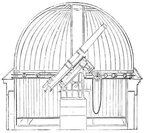
Fig. 151.—Dome.
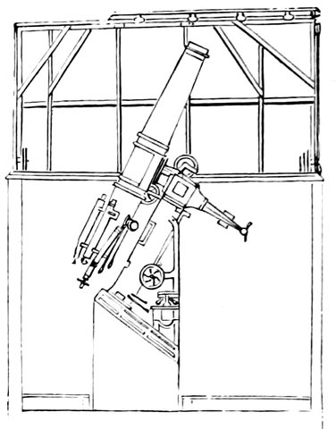
Fig. 152.—Drum.
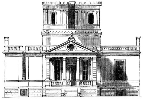
Fig. 153.—New Cincinnati Observatory—Front elevation, showing exterior of Drum.
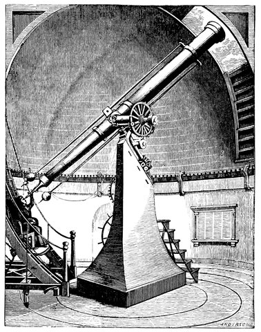
Fig. 154.—Cambridge (U.S.) Equatorial, showing Observing Chair and rails.
The equatorial and the building to contain it have now been described, but there is another piece of apparatus which is required as much as any adjunct to the equatorial, and that is the chair or rest for the observer. Since the 340telescope may be sometimes horizontal, and at other times vertical, the observer must be at one time in an upright position, and at another lying down and looking straight up. A rest is required which will carry the observer in these or in intermediate positions. A convenient form of rest for small telescopes consists of a seat like that of a chair, with a support moving on hinges at the back of the seat; a rack motion fixes this at any inclination, so that the observer’s back can be sustained in any position, between upright and nearly horizontal. The seat with its back slides on two straight bars of wood, sloping upwards from near the ground at an angle of about 30°, and about 8ft. long; these are supported at their upper ends by uprights of wood, and at their lower ends in the same manner by shorter pieces. These four uprights are firmly braced together, and have castors at the bottom. A rack is cut on one of the inclined slides, and a catch falls into it, so as to fix the seat at any height to which it is placed.
In larger observatories a more elaborate arrangement is adopted, the rails, on which the seat moves, are curved to form part of a circle, having the centre of motion of the telescope for its centre; as the seat with its back is moved up or down on the curved slides, its inclination is changed, so that the observer is always in a favourable position for observing. The seat on its frame runs on circular rails round the pier of the telescope, so that the eyepiece can be followed round as the telescope moves in following a star. A winch by the side of the observer, acting on teeth on one of the rails, enables him to move the chair along, and a similar arrangement enables him to raise or lower the seat on the slides without removing from his place. A steady mounting for 341the telescope, and a comfortable seat for the observer, are the two things without which a telescope is almost useless.
The observing chair is well seen in the engravings of Mr. Newall’s and the Cambridge telescopes. The eyepieces and micrometer can be carried on the rest, close to the observer, when much trouble is saved in moving about for things in the dark; and for the same reason there should be a place for everything in the observatory, and everything in its place.
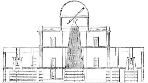
Fig. 155.—Section of Main Building—United States Naval Observatory, showing support of Equatorial.
The very high magnifying power employed upon equatorials in the finest states of the air necessitates a very firm foundation for the central pillar. The best position for such an instrument is on the ground, but it is almost always necessary to make them high in order to be able to sweep the whole horizon. The accompanying woodcut will give an idea of the precautions that have to be taken under these circumstances. A solid pillar 342must be carried up from a concrete foundation, and there must be no contact between this and the walls or floors of the building, when the dome thus occupies the centre of the observatory. The other rooms, generally built adjoining the equatorial room, radiate from the dome, east and west, not sufficiently high to interfere with the outlook of the equatorial. In one of these the transit is placed; an opening is made in the walls and roof, so that it has an unimpeded view when swung from north through the zenith to south, and this is closed when the instrument is not in use by shutters similar to those of the dome.
At one of the very earliest meetings of the Royal Society, the difficulties of mounting the long focus lenses of Huyghens being under discussion, Hooke pointed out that all difficulties would be done away with if instead of giving movement to the huge telescope itself, a plane mirror were made to move in front of it. This idea has taken two centuries to bear fruit, and now all acknowledge its excellence.
One of the most recent additions to astronomical tools is the Siderostat, the name given to the instrument suggested by Hooke. By its means we can make the sun or stars remain virtually fixed in a horizontal telescope fixed in the plane of the meridian to the south of the instrument, instead of requiring the usual ponderous mounting for keeping a star in the field of view.
It consists of a mirror driven by clockwork so as to continually reflect the beam of light coming from a star, or other celestial object, in the same direction; the principle consisting in so moving the mirror that its normal shall always bisect the angle subtended at the mirror by the object and the telescope or other apparatus on which the object is reflected.
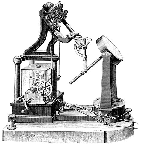
Fig. 156.—Foucault’s Siderostat.
It was Foucault who, towards the end of his life, thought of the immense use of an instrument of this kind as a substitute for the motion of equatorials; he, however, unfortunately did not live to see his ideas realized, but the Commission for the purpose of carrying out the publication of the works of Foucault directed Mr. Eichens to construct a siderostat, and this one was presented to the Academy of Science on December 13th, 1869, and is now at the Paris Observatory. Since that date others have been produced, and they have every chance of coming largely into use, especially in physical astronomy. Fig. 156 shows the elevation of the instrument, 345the mirror of which, in the case of the instrument at Paris, is thirty centimetres in diameter, and is supported by a horizontal axis upon two uprights, which are capable of revolving freely upon their base. The back of the mounting of the mirror has an extension in the form of a rod at right angles to it, by which it is connected with the clock, which moves the mirror through the medium of a fork jointed at the bottom of the polar axis.
The length of the fork is exactly equal to the distance from the horizontal axis of the mirror to the axis of the joint of the fork to the polar axis, and the direction of the line joining these two points is the direction in which the reflected ray is required to proceed. The fork is moved on its joint to such a position that its axis points to the object to be viewed, and, being carried by a polar axis, it remains pointing to that object as long as the clock drives it, in the same manner as a telescope would do on the same mounting. Then, since the distance from the axis of the mirror to the joint of the fork is equal to the distance from the latter point to the axis of its joint to the sliding tube on the directing rod, an isosceles triangle is formed having the directing rod at its base; the angles at the base are therefore equal to each other.
Further, if we imagine a line drawn in continuation of the axis of the fork towards the object, then the angle made by this line and that from the axis of the mirror to the elbow joint of the fork (the direction of the reflected ray) will be equal to the two angles at the base of the isosceles triangle; and, since they are equal to each other, the angle made by the directing rod and the axis of the fork (or the incident ray) from the object, is equal to half the angle made by the latter ray and the direction of the reflected ray; and if lines are drawn through the surface 346of the mirror in continuation of the directing rod and the line from the elbow joint to the axis of the mirror; and a line to the point of intersection be drawn from the object, this last line will be parallel to the axis of the fork, and the angle it makes with the continuation of the directing rod, or normal to the surface of the mirror, will be half the angle made by it and the line representing the reflected ray. Therefore the angle made by the incident ray and the required direction of the reflected ray is always bisected by the normal, so that the reflected ray is constant in the required direction.
The clock is driven in the usual manner by a weight. A rod carries the motion up to the system of wheels by which the polar axis is rotated. As this axis rotates it carries with it the fork, which transmits the required motion to the mirror. And as the fork alters its direction the tube slides upon the directing rod, thus altering the inclination of the mirror. In order to vary the position of the mirror without stopping the instrument there are slow motion rods or cords proceeding from the instrument which may be carried to any distance desirable.
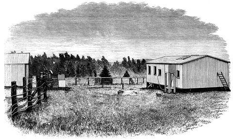
Fig. 157.—The Siderostat at Lord Lindsay’s Observatory.
The polar axis is set in the meridian similarly to an equatorial telescope, the whole apparatus being firmly mounted upon a massive stone pillar which is set several feet in the ground, and rests upon a bed of concrete, if the soil is light. A house upon wheels, running upon a tramway, is used to protect the instrument from the weather, and when in use this hut is run back to the north, leaving the siderostat exposed. In the north wall of the observatory is a window, and the telescope is mounted horizontally opposite to it: so the observer can seat himself comfortably at his work, and by his guide 348rods direct the mirror of the siderostat to almost any part of the sky, viewing any object in the eyepiece of his telescope without altering his position. In spectroscopy and celestial photography its use is of immense importance, for in these researches the image of an object is required to be kept steadily on the slit of the spectroscope or on the photographic plate, and for this purpose a very strongly-made and accurate clock is required to drive the telescope and mounting, which are necessarily made heavy and massive to prevent flexure and vibration. The siderostat, on the other hand, is extremely light, without tube or accessories, and a light, delicate clock is able to drive it with accuracy, while the heavy telescope and its adjuncts are at rest in one position. The sun and stars can, therefore, as it were, be “laid on” to the observer’s study to be viewed without the shifting of the observatory roof and equatorial, or of the observing chair, which brings its occupant sometimes into most uneasy positions.
We figure to ourselves the future of the physical observatory in the shape of an ordinary room with siderostat outside throwing sunlight or rays from whatever object we wash into any fixed instrument at the pleasure of the observer. There are, however, inconveniences attending its use in some cases; for instance, in measuring the position of double stars, the diurnal motion gradually changes their position in the field of the telescope, so that a new zero must be constantly taken or else the time of observation noted and the necessary corrections made.
The equatorial enables us to make not only physical observations, but differential observations of the most absolute accuracy.
First we may touch upon the physical observations made with the eyepiece alone—star-gazing, in fact. The Sun first claims our attention: our dependence on him for the light of day, for heat, and for in fact almost everything we enjoy, urges us to inquire into the physics of this magnificent object. Precautions must however be taken; more than one observer has already been blinded by the intense light and heat, and some solar eyepiece must be used. For small telescopes up to two inches, a dark glass placed between the eye and the eyepiece is sufficiently safe; for larger apertures, the diagonal reflector, or Dawes’ solar eyepiece, already described, comes into requisition. Another method of viewing the sun is to focus the sun’s image with the ordinary eyepiece on a sheet of paper or card, or, better still, on a surface of plaster of Paris carefully smoothed. The bright ridges or streaks, usually seen in spotted regions near the edge, called the faculæ, and the mottled surface, appearing, according to Nasmyth, like a number 350of interlacing willow-leaves—the minute “granules” of Dawes, are best seen with a blue glass; but for observing the delicately-tinted veils in the umbræ of the spots a glass of neutral tint should be used.
The Moon is a fine object even in small telescopes. The best observing time is near the quarters, as near full moon the sun shines on the surface so nearly in the same direction as that in which we look, that there is no light and shade to throw objects into view. Hours may be spent in examining the craters, rilles, and valleys on the surface, accompanied with a good descriptive map or such a book as that which Mr. Neison has recently published.
The planets also come in for their share of examination. Mercury is so near the sun as seldom to be seen. Venus in small telescopes is only interesting with reference to her changes, like the moon, but in larger ones with great care the spots are visible. Mars is interesting as being so near a counterpart of our own planet. On it we see the polar snows, continents and seas, partially obscured by clouds, and these appearances are brought under our view in succession by the rotation of the planet. With a good six-inch glass and a power of 200 when the air is pure and the opposition is favourable, there is no difficulty in making out the coast-lines, and the various tones of shade on the water surface may be observed, showing that here the sea is tranquil, and there it is driven by storms. Up to very lately it was the only planet of considerable size further off the sun than Venus that was supposed to have no satellite; two of these bodies have however been lately discovered by Hall with the large Washington refractor of twenty-six inches diameter, and they appear to be the tiniest 351celestial bodies known, one of them in all probability not exceeding 10 miles in diameter. Jupiter and Saturn are very conspicuous objects, and the eclipses, transits, and occultations of the moons, and the belts of the former and rings of the latter, are among the most interesting phenomena revealed to us by our telescopes, while the delicate markings on the third satellite of Jupiter furnish us with one of the most difficult tests of definition. Uranus and Neptune are only just seen in small telescopes, and even in spite of the use of larger ones, we are in ignorance of much relating to these planets. The amateur will do well to attack all these with that charming book, the Rev. T. W. Webb’s Celestial Objects for Common Telescopes, in his hand.
To observe the fainter satellites of the brighter planets, or, indeed, faint objects generally, near very bright ones, the bright object may be screened by a metallic bar, or red or blue glass placed in the common focus.
So much with regard to our own system. When we leave it we are confounded with the wealth of nebulæ, star-clusters, and single or multiple systems of stars, which await our scrutiny. With the stars, not much can be done without further assistance than the eyepiece alone. The colours of stars may however be observed, and for this purpose a chromatic scale has been proposed, and a memoir thereon written, by Admiral Smyth, for comparison with the stars. The colour of a star must not be confused with the colours—often very vivid—produced by scintillations, these rapid changes of brightness and colour depending on atmospheric causes. Of the large stars, Sirius, Vega and Regulus are white, while Aldebaran and Betelgueux are red. In many double and multiple stars however the contrast of colours shows 352up beautifully; in β Cygni for instance we have a yellow and blue star, in γ Leonis, a yellow and a green star; and of such there are numerous examples.
Interesting as all these observations are, a new life and utility are thrown into them when instead of using a simple eyepiece the wire micrometer is introduced. This, as we have before stated, generally consists of one wire, or two parallel wires, fixed, and one or two other wires at right angles to these, movable across the field. This micrometer is used in connection with a part of the eyepiece end of the telescope, which has now to be described. This is a circle, the fineness of the graduation of which increases with the size of the telescope, read by two or four verniers. The circle is fixed to the telescope, while the verniers are attached to the eyepiece, carrying the micrometer, which is rotated by a rack and pinion.
The whole system of position circle (as it is called) and wire micrometer, is in adjustment when (1) the single or double fixed wires and the movable ones cross in the centre of the field, and (2) when with a star travelling along the single fixed or between the two fixed wires, the upper vernier reads 180 and the lower one reads zero.
This motion across the field gives the direction of a parallel of declination; that is to say, it gives a line parallel to the celestial equator, and, knowing that, one will be able at once, by allowing the object to pass through the field of view, to get this datum line. For instance, supposing the whole instrument is turned round on the end of the telescope, so that one of the two wires x and y, Fig. 104, at right angles to the thin wires for measuring distance, shall lie on a star during all its motion across the field of view; then those two wires, 353being parallel to the star’s motion, will represent two parallels of declination; and we use the direction of the parallels of declination to determine the datum point at right angles to them, that is, the north point of the field. We have then a position micrometer, that is, one in which the field of view is divided into four quadrants, called north preceding, north following, south preceding, and south following, because if there be an object at the central point it will be preceded and followed by those in the various quadrants. The movable wires lie on meridians and the fixed ones on parallels when adjusted as above.
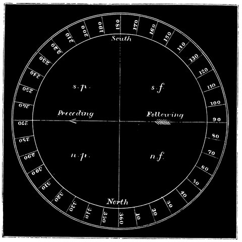
Fig. 158.—Position Circle.
The position circle is often attached to, and forms part of, the micrometer instead of being fixed to the telescope, and in screwing it on from time to time, the adjustment of the zero changes, and the index error 354must be found each time the micrometer is put on the telescope.
In practice it is usual to take the north and south line as the datum line, and positions are always expressed in degrees from the north round by east 90°, south 180°, and west 270°, to north again in the direction contrary to that of the hands of a clock.
The angle from the east and west line being found by the micrometer, 90° is either added or subtracted, to give the angular measurement from north. But to make these measurements we want a clock; a clock which, when we have got one of these objects in the middle of the field of view, shall keep it there, and enable the telescope to keep any object that we may wish to observe fixed absolutely in the field of view. But in the case of faint objects this is not enough. We want not only to see the object, but also the wires we have referred to. Now then the illuminating-lamp and bright wires, if necessary, come into use.
The following, Fig. 159, will show how we proceed if we merely wish to measure a distance, the value of the divisions of the micrometer screw having been previously determined by allowing an equatorial star to transit. It represents the position of the central and the movable wire when the shadow thrown by the central hill of the the lunar crater Copernicus is being measured to determine the height of the hill above the floor of the crater. It has been necessary to let the fixed wire lie along the shadow; this has been done by turning the micrometer; but there is no occasion to read the vernier.
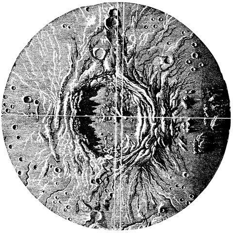
Fig. 159.—How the Length of a Shadow thrown by a Lunar Hill is measured.
Except on the finest of nights the stars shake in the field of view or appear woolly, and even on good nights the readings made by a practised eye often differ, inter se, more than would be thought possible. In measuring distances we have supposed for simplicity that we find the distance that one wire has to be moved from coincidence with the fixed wire from one point to another, and theoretically speaking the pointer should point to O on the screw head when the wires are over each other, and then when the wires are on the points, the reading of the screw head divided by the number of divisions corresponding to 1˝ will give the distance of the points in seconds of arc. But in practice it is unnecessary to adjust the head to O when the wires coincide, and the unequal expansion of the metals of the instrument, due to changes of temperature, would soon disarrange it. It is also somewhat difficult to say when the wires exactly coincide, 356and an error in this will affect the distance between the points. It is therefore found best to only roughly adjust the screw head to O, and then open out the wires until they are on the points and take a reading, say twenty-two; the screw is then turned, in the opposite direction and the movable wire passed over to the other side of the fixed one, and another reading taken, say eighty-two; now the screw has to be moved in the direction which decreases the readings on its head from one hundred downwards, as the distance of the wires increases, so that we must subtract the reading eighty-two from a hundred to give the number of divisions from the O through which the screw is turned, and the reading in this direction we will call the indirect reading, in contradistinction to the direct reading taken at first. So far we have got a reading of twenty-two direct and eighteen indirect, which means that we have moved the screw from twenty-two on one side of O to eighteen on the other side, or through forty divisions, and in doing so the movable wire has been moved from the distance of the two points on one side of the fixed wire to the same distance on the other, or through double the distance required. Therefore forty divisions is the measure of twice the distance, and the half of forty, or twenty divisions, is the measure of the distance itself between the two points to which our attention has been directed, whether stars, craters in the moon, spots on the sun, and the like.
Let us consider what is gained by this method over a measure taken by coincidence of the wires as a starting-point, and opening out the wires until they cut the points. In the method we have just described there are two chances of error in taking the measurements—the direct and indirect; but the result obtained is divided 357by two, so that the error is also halved in the final result. Now by taking the coincidence of the wires as the zero, or starting-point, the measure is open to two errors, as in the last case—the error of measurement of the points, plus the error of coincidence of wires, an error often of considerable amount, especially as the warmth of the face and breath causes considerable alteration in the parts of the instrument, making a new reading of coincidence necessary at each reading of distance. As the result is not divided by two, as in the first case, the two errors remain undivided, so we may say that there is the half of two errors in one case and two whole errors in the other.
Here then we use the micrometer to measure distances; but from a very short acquaintance with the work of an equatorial it will at once be seen that one wants to do something else besides measure distances. For instance, if we take the case of the planet Saturn, it would be an object of interest to us to determine how many turns, or parts of a turn, of the screw will give the exact diameter of the different rings; but we might want to know the exact angle made by the axis with the direction of the planet’s motion, across the field, or with, the north and south line.
If we have first got the reading when the wires are in a parallel of declination, and then bring Saturn back again to the middle of the field and alter the direction of the wires until they are parallel to the major axis of the ring, we can read off the position on the circle, and on subtracting the first reading from this, we get the angle through which we have moved the wires, made by the direction of the ring with the parallel of declination, which is the angle required. We are thus 358not only able to determine the various measurements of the diameter of the outer ring by one edge of the ring falling on one of the fine wires, and the other edge on the other wire, but, by the position circle outside the micrometer we can determine exactly how far we have moved that system, and thus the angle formed by the axis of the ring of the planet at that particular time.
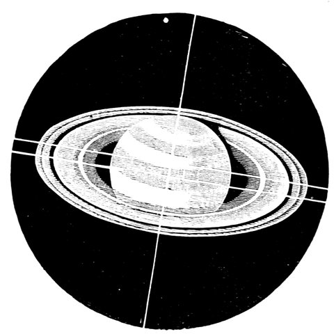
Fig. 160.—The Determination of the Angle of Position of the axis of Saturn’s Ring.
The uses of the position micrometer as it is called are very various. In examination of the sun it is used to ascertain the position of spots on the surface, and the rate of their motion and change. The lunar craters require mapping, and their distances and bearing from certain fixed points measuring, for this then the position micrometer comes into use.
The varying diameters and the inclinations of the axes of the planets and the periods of revolution of the satellites are determined, and the position of their orbits fixed, in like manner. When a comet appears it is of importance to determine not only the direction of its 359motion among the stars, but the position of its axis of figure, and the angles of position and dimensions of its jets. The following diagram gives an example of the manner in which the position of its axis of figure is determined. First the nucleus is made to run along the fixed wire, so that it may be seen that the north vernier truly reads zero under this condition; if it does not its index error is noted. The system of wires is then rotated till one of the wires passes through the nucleus and fairly bisects the dark part behind the nucleus.
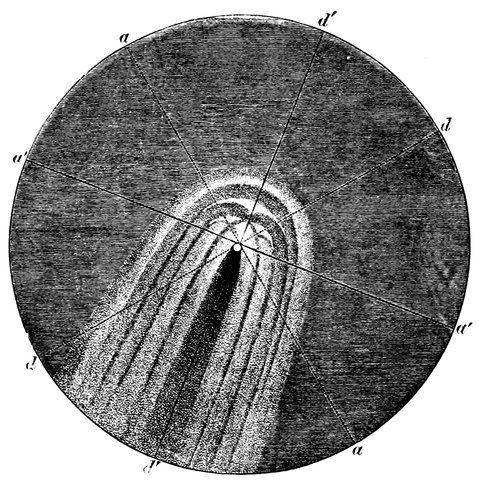
Fig. 161.—Measurement of the Angle of Position of the Axis of Figure of a Comet, a a, positions of fixed wire when the north vernier is at zero; d d position of movable wire under like conditions; a´ a´, d´ d´, positions of these wires which enable the angle of position of the comet’s axis to be measured. The angle a a´ or d d´ is the angle required.
It need scarcely be said that these observations are also of importance with reference to the motion of the binary stars, those compound bodies, those suns revolving round each other, the discovery of which we owe 360to the elder Herschel. We may thus have two stars a small distance apart; at another time we may have them closer still; and at another we may have them gradually separating, with their relative position completely changed. By means of the wire micrometer and the arrangement for turning the system of wires into different positions with regard to the parallel of declination, we have a means of determining the positions occupied by the binary stars in all parts of their apparent orbit, as well as their distances in seconds of arc. It is found, however, by experience that the errors of observation made in estimating distances are so large, relatively to the very small quantities measured, that it is absolutely necessary to make the determination of the orbit depend chiefly on the positions. And this is done in the following way.
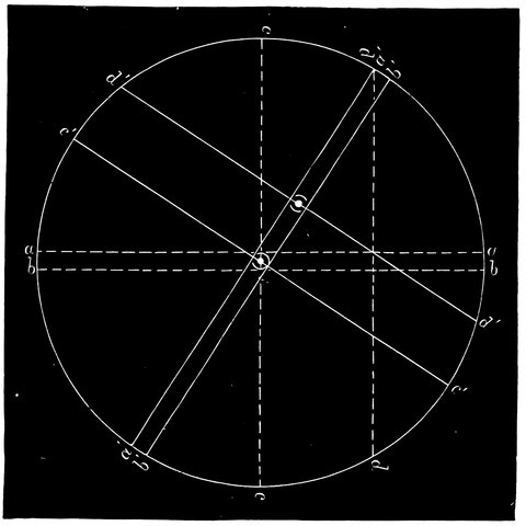
Fig. 162.—Double Star Measurement, a a, b b, first position of fixed, double wire when the vernier reads 0°, and the star runs between the wires; c c, d d, first position of movable wires. a´ a´, b´ b´, new position of fixed double wire which determines the angle of position; c´ c´, d´ d´, new positions of the movable wires which measure the distance.
361It is possible, by knowing the position angles at different dates, to find the angular velocity, and since the areas described by the radius vector are equal in equal times, the length of the radius vector must vary inversely as the square root of the angular velocity, and by taking a number of positions on the orbit of known angular velocity, we can set off radii vectores, and construct an ellipse, or part of one, by drawing a curve through the ends of the radii vectores; and from the part of the ellipse so constructed it is possible to make a good guess at the remainder. The angular size of this ellipse is obtained from the average of all the measures of distance of the stars. This ellipse is then the apparent ellipse described by the star, and the form and position of the true ellipse can be constructed from it from the consideration of the position of the larger star (which must really be the focus), with reference to the focus of the apparent ellipse; for if an ellipse be seen or projected on a plane other than its own, its real foci will no longer coincide with the foci of the projected ellipse.
The methods adopted in practice, for which we must refer the reader to other works on the subject, are, however, much more laborious and lengthy than the above outline, which is intended merely to show the possibility, or the faint outline of a method of constructing the real ellipse. When the real ellipse or orbit is known, it is then of course possible to predict the relative positions of the two components. Let us consider in some little detail the actual work of measuring a double star.
A useful form for entering observations upon, as taken, is the following, which is copied from one actually used.
| Distance. | |||
|---|---|---|---|
| Direct. | Indirect. | ½ Diff. | |
| 17 | 97 | 10 | |
| 16 | 97 | 9·5 | |
| ——————— | |||
| 9·75 | mean. | ||
| Readings. | |||||
|---|---|---|---|---|---|
| 170·1 | |||||
| 170· | |||||
| 169·5 | |||||
| 169·8 | |||||
| ————— | |||||
| 4) | 679·4 | ||||
| ————— | |||||
| 169·8 | |||||
| 109·8 | |||||
| 90·0 | |||||
| ————— | |||||
| 19·8 | |||||
| 169·8 | Position = | 150° | |||
| 19·8 | |||||
| ————— | Distance = | 1˝·828. | |||
| 150 | |||||
| Distance. | |||
|---|---|---|---|
| Direct. | Indirect. | ½ Diff. | |
| 12·5 | 99·5 | 6·5 | |
| 12·6 | 99·2 | 6·7 | |
| ——————— | |||
| 6·6 | mean. | ||
| Readings. | |||||
|---|---|---|---|---|---|
| 79·5 | |||||
| 81·5 | |||||
| 81·2 | |||||
| ————— | |||||
| 3) | 242·2 | ||||
| ————— | |||||
| 81·1 | mean. | ||||
| 88·9 | |||||
| 90·0 | |||||
| ————— | |||||
| -1·1 | |||||
| 81·1 | |||||
| -1·1 | |||||
| ————— | |||||
| 82·2 | Position = | 262°·2. | |||
| 180·0 | |||||
| ————— | Distance = | 1´·237. | |||
| 262·2 | |||||
363The star having been found, the date and decimal of the year are entered at the top, and a position taken by bringing the thick wires parallel to the stars. A distance—say direct—is then taken, and the degrees of position 170°·1, and divisions of the micrometer screw seventeen, read off with the assistance of a lamp and entered in their proper columns. The micrometer is then disarranged and a new measure of position and an indirect distance taken, and so on. At the end of the readings, or at any convenient time, the zero for position is found by turning the micrometer until the wires are approximately horizontal, and then allowing a star to traverse the field by its own motion, or rather that of the earth, and bringing the thick wires parallel to its direction of motion; this may be more conveniently done by means of the slow-motion handle of the telescope in R. A., which gives one the power of apparently making the star traverse backwards and forwards in the field. The position of the wires is altered until the star runs along one of them. The position is then read off and entered as the zero. In describing the adjustments of the position circle we made the vernier read 0° when the star runs along the wire, for that is practically the only datum line attainable; since, however, the angles are reckoned from the north, it is convenient to set the circle to read 90° when the star runs along the wire, so that it reads 0° when the wires are north and south.
Now as positions are measured from north 0° in a direction contrary to that of the hands of a watch, and an astronomical telescope inverts, we repeat the bottom of the field is 0°, the right 90°, and so on; now the reading just taken for zero is the reading when the wires are E. and W., so that we must deduct 90° from 364this reading, giving 19°·8 as the reading of the circle when the wires were north and south, or in the position of the real zero of the field. Of course theoretically the micrometer ought to read 0° when the wires are north and south, but in screwing on the instrument from night to night it never comes exactly to the same place, so that it is found easier to make the requisite correction for index error rather than alter the eye end of the telescope to adjustment every night. The readings of position must therefore be corrected by the number of degrees noted when the wires are at the real zero, which in the case in point is 19°·8, which may be called the index error.
It is also obvious that the micrometer may be turned through 180° and still have its wires parallel to any particular line. The position of the stars also depends upon the star fixed on for the centre round which our degrees are counted; for in the case of two stars just one over the other in the field of view, if we take the upper one as centre, then the position of the system is 0°, but if the lower one, then it is 180°; in the case of two equal or nearly equal stars, it is difficult to say which shall be considered as centre, and so the position given by two different persons might differ by 180°. There are also generally two verniers on the position circle, one on each side, and these of course give readings 180° different from each other, so that 180° has often to be added or subtracted from the calculated result to give the true position. All that is really measured by the position micrometer is the relative position of the line joining the stars with the N. and S. line. In order, therefore, to find, whether 180° should be added or not, a circle is printed on the form, with two bars across for a guide to the eye, and the stars as seen are roughly 365dotted down in their apparent position—in the case in point about 150°. Our readings being now made, we first take a mean of those of position, which is 169°·8, nearly, and the zero is 109°·8; deduct 90° from this to give the reading of the N. and S. line 19°·8, then we deduct this from the mean of position, 169·8, giving us 150° as the position angle of the stars.
It often happens that the observed zero is less than 90°, and then we must add 360° to it before subtracting the 90°, or what is perhaps best, subtract the observed zero from 90°, and treat the result as a minus quantity, and therefore add it to the mean of position readings instead of subtracting as usual. The observations of the second star give a case in point: the zero is 88°·9, and subtracting this from 90°, we get 1°·1; we put this down as -1°·1 to distinguish it from a result when 90° is subtracted from the zero; it is then added to the mean of position readings 81°·1, giving 82°·2, but on reference to the dots showing the approximate position of the stars, it is seen that 180° must be added to their result, giving 262°·2 as the position of the stars.
Now as to distance, take the case of the second star. Subtract the first indirect reading from 100°, giving 0·5, and add this to the direct reading, 12·5, making 13·0, which is the difference between the two readings taken on either side of the fixed wire; the half of this, 6·5, is placed in the next column, and the same process is repeated with the next two readings: a mean of these is then taken, which is 6·6 for the number of divisions corresponding to the distance of the stars. In the micrometer used in this case, 5·3 divisions go to 1˝, so that 6·6 is divided by 5·3, giving 1˝·237 as the distance. A table showing the value in seconds of the divisions from 366one to twenty or more, saves much time in making distance calculations; the following is the commencement of a table of this kind where 5·3 divisions correspond to 1˝.
| Divisions of micrometer. | 0 | ·1 | ·2 | ·3 | ·4 | ·5 | ·6 | ·7 | ·8 | ·9 |
| 0 | 0·000 | ·018 | ·037 | ·056 | ·075 | ·093 | ·112 | ·131 | ·150 | ·168 |
| 1 | 0·187 | ·205 | ·224 | ·243 | ·262 | ·280 | ·299 | ·318 | ·337 | ·356 |
| 2 | 0·375 | ·393 | ·412 | ·431 | ·450 | ·468 | ·487 | ·506 | ·525 | ·543 |
In the first column are the divisions, and in the top horizontal line the parts of a division, and the number indicated by any two figures consulted is the corresponding number of seconds of arc. In the case of a half difference of 2·3 we look along the line commencing at 2 until we get under 3, when we get 0˝·431 as the seconds corresponding to 2·3 divisions.
It is necessary to adjust the quantity of light from the lamp in the field, so that the wires are sufficiently visible while the stars are not put out by too much illumination; for the majority of stars a red glass before the lamp is best. This gives a field of view which renders the wires visible without masking the stars, but a green or blue light is sometimes very serviceable. A shaded lamp should be used for reading the circles on the micrometer, so as not to injure the sensitiveness of the eye by diffused light in the observatory. A lamp fixed to the telescope, having its light reflected on the circles, but otherwise covered up, is a great advantage over the hand-lamp. In very faint stars, which are masked by a light in the field sufficient to see the wires, the wires can be illuminated in the same manner as in the transit, but 367there is this disadvantage—the fine wires appear much thickened by irradiation, so that distances, especially of close stars, become difficult to take.
We come now to the differential observations made with the equatorial. Let us explain what is meant. Suppose it is desired to determine with the utmost accuracy the position of a new comet in the sky. If we take an ordinary equatorial, or an extraordinary equatorial (excepting probably the fine equatorial at Greenwich), and try to determine its place by means of the circles, its distance from the meridian giving its right ascension and its distance from the equator giving its declination, we shall be several seconds out, on account of want of rigidity of its parts; but if we do it by means of such an instrument as the transit circle at Greenwich, we wait till the comet is exactly on the meridian, and determine its position in the way already described.
As a matter of fact, however, the transit circle is not the instrument usually used for this purpose, but the equatorial. We do not however just bring the comet or other object into the middle of the field and then read off the circles, but we differentiate from the positions of known stars; so that all that has to be done in order to get as perfect a place for the comet as can be got for it by waiting till it comes to the meridian—which perhaps it will do in the day-time, when it will not be visible at all—is to determine its distance in right ascension and declination from a known star, by means of a micrometer. Of course one will choose the brightest part of the comet and a well-known star, the place of which has been determined either by its appearance in one of the catalogues, or by special transit 368observations made in that behalf. We then by the position micrometer determine its angle of position and distance from the known star at a time carefully noted, or we measure the difference in right ascension and the difference in declination.
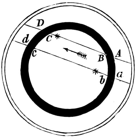
Fig. 163.—Ring Micrometer.
Continental astronomers have another way of doing this which we will attempt to explain. Suppose we wish to find the difference in declination of a star and Jupiter, we place the ring, A D, Fig. 163, in the eyepiece of the telescope and watch the passage of Jupiter and the star over this ring micrometer. It will be clear that, as the motion of the heavens is perfectly uniform, it will take very much less time for the star to travel over the ring from B to C than it will for Jupiter to travel over the ring from b to c, because the star is further from the centre; and by taking the time of external and internal contact at each side of the ring, the details of which we need not enter upon here, the Continental astronomers are in the habit of making differential observations of the minutest accuracy by means of this ring micrometer, whilst we prefer to make them by the wire micrometer.
We have now gone down the stream of time, from Hipparchus to our own days. We find now enormous telescopes which enable us to see and examine celestial bodies lying at distances so great that the mention of them conveys little to the mind. We find also perfect systems of determining their places. The following chapters will show, however, that modern astronomy has not been contented with annexing those two branches of physics which have enabled us to make the object-glass and the clock, and another still which enables us to make that clock record its own time with accuracy.
These applications of Science have been effected for the purpose either of determining with accuracy the motion and positions of the heavenly bodies or of enabling us to investigate their appearances under the best possible conditions. The other class of observations to which we have now to refer, have to do with the quantity and the quality of the vibrations which these bodies impart to the ether, by virtue of which vibrations they are visible to us.
We began by measurement of angles, we end with a wide range of instruments illustrating the application of 372almost every branch of physical as well as of mathematical science. In modern observatories applications of the laws of Optics, Heat, Chemistry and Electricity, are met with at every turn.
Each introduction of a new instrument, or of a new method of attack, has by no means abolished the preexisting one; accretion rather than substitution has been the rule. On the one hand, measurement of angles goes on now more diligently than it did in the days of Hipparchus, but the angles are better measured, because the telescope has been added to the divided arc. Time is as necessary now as it was in the days of the clepsydra, but now we make a pendulum divide its flow into equal intervals and electricity record it. On the other hand, the colours of the stars are noted as carefully now as they were before the spectroscope was applied to the telescope, but now we study the spectrum and inquire into the cause of the colour. The growth of the power of the telescope as an instrument for eye observations has gone on, although now almost all phenomena can be photographically recorded.
The uses to which all astronomical instruments may be put may be roughly separated into two large groups:—
I. They may be used to study the positions, motions, and sizes of the various masses of matter in the universe. Here we are studying celestial mechanics or mechanical astronomy, and with these we have already dealt.
II. They maybe used to study the motions of the molecules of which these various masses are built up, to learn their quality, arrangement, and motions. Here we are studying celestial physics, or physical astronomy.
It is with this latter branch that we now have to do.
373First we have to deal with the quantity and intensity of the ethereal vibrations set up by the constituent molecules of these distant bodies. We wish to compare the quantity of light given out by one star with that given out by another. We wish, say, to compare the light of Mars with the light of Saturn; we are landed in the science of photometry, which for terrestrial light-sources has been so admirably investigated by Rumford, Bouguer, and others.
Here we deal with that radiation from each body which affects the eye—but by no means the total radiation. This is a point of very considerable importance.
Modern science recognises that in the radiation from all bodies which give us white light there is so great a difference of length of wave in the vibrations that different effects are produced on different bodies. Thus white light is a compound thing containing long waves with which heat phenomena are associated, waves of medium length to which alone the eye is tuned, and short waves which have a decided action on some metallic salts which are unaffected by the others.
To thus examine the constituents of a beam of light a lantern, with a lime-light or electric light, may be used for throwing a constant beam; we may then produce an image of the cylinders of lime or the carbon points in the lantern on a piece of paper or a screen, and our eyes will tell us that this is an instance of how the radiations from any incandescent substance are competent to give us light. We receive all the rays to which our eyes are tuned and we see a white image on the screen. We shall see also that the light is more intense than that of a candle, in other words that the radiation from the light-sources we have named is very great.
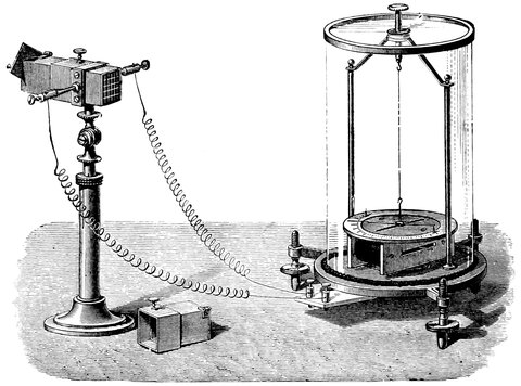
Fig. 164.—Thermopile and Galvanometer.
Now let us insert in front of the lantern a piece of deep red glass, that is, glass which allows only the red constituents of the white light to pass. Now if a thermo-electric pile, Fig. 164, be introduced into the beam we shall see that the needle of the galvanometer will alter its position. Now, why does the needle turn? This is not the place for giving all the details of this instrument, but it is sufficient to say (1) that the needle moves whenever a current of electricity flows through the coil of wire surrounding the needles, and (2) that the pile consists of a number of bars of antimony and bismuth joined at the alternate ends, and whenever one end of the pile is heated more than the other, a current of electricity is caused to flow. Such is the delicacy of the instrument, that the heat radiated from the hand, held some 375yards away from it, is sufficient to set the needle swinging violently; this then acts as a most delicate thermometer. In this case it shows that heat effects are produced by the red constituents of the light from the lamp.
Now replace the thermopile by a glass plate coated with a salt of silver in the ordinary way adopted by photographers. No effect will be produced.
Replace the red glass by a blue one. If the light is now allowed to fall on the photographic plate, its effect is to decompose, or alter the arrangement of, the atoms of silver, so that on applying the developing solution, the silver compound is reduced to its metallic state on the places where the light has acted; and thus, if the image of the light-source has been focussed on the plate, a photograph of it is the result. If the thermopile is brought into the beam it will be now as insensitive to the blue light as the photographic plate was to the red light in the former case. We have therefore three kinds of effects produced, viz., light, heat, and chemical or actinic action, and when light is passed through a prism, these three different radiations, or energies, are most developed in three different portions of the spectrum.
If indeed a small spectrum be thrown on the screen and the different colours are examined with the thermopile, it will be found that as long as we allow it to remain at the blue end of the spectrum, there will be no effect on the galvanometer, but if instead of holding it at the blue end we bring it towards the red, the galvanometer needle is deflected from its normal position, to that it had when the red rays fell on it, showing that it is beyond all doubt the red rays and not the blue to which it is sensitive. Where then in the spectrum are 376the rays which affect the photographic plate? We can at once settle this point. If one be placed in the spectrum for a short time, and then developed, it will be found to be affected only in the part on which the blue rays have fallen. Indeed to demonstrate this no lamp is necessary.
If for half-an-hour or so two pieces of sensitive paper are placed in the daylight, one covered with red glass, and the other with violet, so that the sunlight is made to travel, in the one case, through red glass, and in the other through violet, it will be found that the violet light will act, and produce a darkening of the paper, while the red glass will preserve the paper below it from all action. This is a proof that the blue end of the spectrum has another kind of energy, a chemical energy, by means of which certain chemicals are decomposed, this is the basis of photography.
These different qualities of light have been utilized by the astronomer. He attaches a thermopile to his telescope and establishes a celestial thermometry. The radiations repay a still more minute examination, and aided by the spectroscope, he is able to study with the utmost certitude the chemical condition of the heavenly host, while the polariscope enables him to acquire information in still another direction. Nor does he end here. He replaces his eye by a sensitive plate, which not only enables him to inquire into the richness of the various bodies in these short waves, but actually to obtain images of them of most marvellous beauty and exactness.
These various lines of work we have to consider in the remaining chapters.
One branch of observatory work is that of determining the relative magnitude of stars, the word magnitude being of course used in a conventional sense for brightness. There are, moreover, stars which vary in brightness or magnitude from time to time; these are called variable stars, and the investigation of the amount and period of variation opens up another use for the equatorial, and an instrument is required for finding the value of the amount of light given by a star at any instant; in fact, a photometer is necessary. The methods of determining the brilliancy of stars are so similar in principle to those employed for ordinary light-sources that the ordinary methods of photometry may be referred to in the first instance. We may determine the relative brilliancy of two or more lights, or we may employ a standard light and refer all other lights to that.
Rumford’s photometer, Fig. 165, is based upon the fact that if the intensity of the shadows of an opaque body be equal, the lights throwing the shadows are equal. Hence the lights are moved towards or from a screen until the shadows are equal; then if the distances from the screen are unequal the lights are unequal, and 378the intensities vary in the inverse ratio of the squares of the distances.
This method is practically carried out in the telescope by reducing the aperture till the stars become invisible, and noting the apertures at which each vanishes in turn.
The most simple method of doing this is that used by Dawes, which is simply an adjustable diaphragm limiting the available area of the object-glass; we can thus view a star, and gradually reduce the aperture until the star is just visible, or until it just disappears, the latter limit being perhaps the most accurate and most usually used; the aperture is read off on the scale attached.
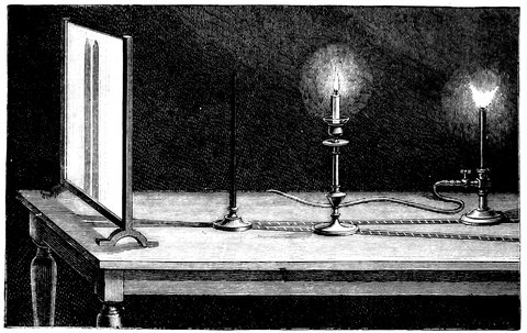
Fig. 165.—Rumford’s Photometer.
The photometer of Mr. Knobel is, however, a very handy one; it consists of a plate of metal having a large V-shaped piece with an angle of 60° cut out of it; 379another plate slides over the first in such a manner that its edge forms a base for the V-shaped opening, thus forming an equilateral triangular hole, which is adjustable at pleasure by moving the second plate. The edge of the moveable plate is divided so that the size of the base of opening is known at once, and its area easily calculated.
The annexed woodcut will give an idea of the second method which is possible.
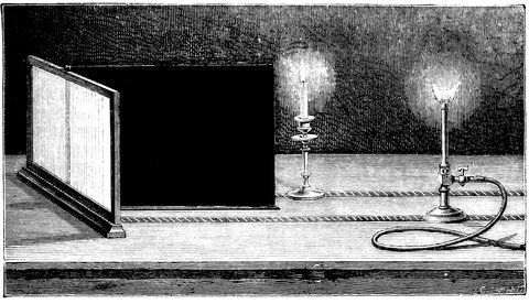
Fig. 166.—Bouguer’s Photometer.
Let the gas flame be supposed to represent a constant light at constant distance; then the intensity of the light to be experimented upon (represented by the candle) is determined by moving it towards or from the mirror till the illumination of both the halves of the porcelain screen is equal. The instrument by which this kind of investigation is carried out by astronomers has been introduced by Zöllner, and is called the Astrophotometer.
380In this the star is compared with a small image of a portion of the flame of a lamp attached to the telescope. It being found that, though the total light emitted by the flame varies with its size, the intensity of the brightest part does not, appreciably. Two artificial stars are formed by means of a pin-hole, a double concave lens, and a double convex lens. These appear in the field by reflexion from the front and back faces of a plate of glass alongside the image of the real star, the light of which passes through the plate. The intensity of the artificial star is varied, first by changing the pin-hole, and finally by two Nicol’s prisms, the colour being first matched with that of the star by means of a third Nicol, with a quartz plate between it and the first of the other two Nicols. The instrument is provided with object-glasses of various sizes (and diaphragms) up to 2¾ inches, and, if fainter stars are to be examined, it can be screwed on to the eyepiece of an equatorial instrument. A second arrangement, like the first, but without the quartz plate arrangement, forms an artificial star from moonlight, for comparison of the light of that body with the artificial star.
So far there is no difficulty, but this measure must be interpreted into magnitude, and we must know what magnitude a star is which just disappears with a given aperture of, say, one inch, and secondly, the ratio of light between the magnitudes, or how much less light is received from a star of the next magnitude in proportion to the given one. If now we were able to start a new scale of magnitude, it would be easy to say that a star just visible with an inch aperture on a fine night shall be called a ninth magnitude star, and fix a certain number of ninth magnitude stars for reference, so that 381the errors induced by hazy nights and variable eyes might be eliminated. An observer on a bad night could limit his aperture on a known star, when he might find that double the area given by an aperture of one inch was required as a limit for one of the stars of reference, and in that case he would know that half the usual amount of light from every star was stopped by atmospheric causes, and he would make the requisite corrections throughout his observations. We might also say that a star of a whole magnitude, greater or less than another, shall give us half or double the amount of light—in fact, that this shall be the ratio between magnitudes. We are not, however, able to make these rules, for an arbitrary scale has been adopted for years, and we can only reduce this scale to a law, in such a manner as not to interfere greatly with the generally received magnitudes.
Amongst the brighter stars there is a close agreement in the estimate of magnitude by different observers, but amongst the higher magnitudes a difference appears. Sir J. Herschel and Admiral Smyth, for instance, go into much higher numbers of magnitudes than Struve; the limit of Admiral Smyth’s vision with his 6-inch telescope was a 16th magnitude, while the limit of Struve’s vision with a 9½-inch telescope he calls a 12th magnitude; the estimates of the latter observer are, however, gaining greater adoption. In order to reduce the relative magnitude to a law, Mr. Pogson[21] took stars differing largely in magnitude, and compared the amount of light from each, and so reduced the ratio between the magnitudes given by Knott and all the best observers.
From this he found that a mean of 2·4 represented 382the ratio, and for reasons given he adopted the quantity 2·512 as a convenient ratio; as he states, “the reciprocal of ½ log. R (in his paper R = the ratio 2·512), a constant continually occurring in photometric formulæ, is in this case exactly 5.”
So far the ratio is established. The next thing is the basis from which to commence reckoning; this Mr. Pogson fixed by reference to Argelander’s catalogued stars, estimated by him at about the 9th magnitude, and with these, comparison is made with the star whose light is measured, and the above constant of ratio applied, which at once gives the magnitude of the measured star. To do this, in Mr. Pogson’s words: “If then any observer will determine for himself the smallest of Argelander’s magnitudes, just visible by fits, on a fine moonless night, with an aperture of one inch, and call this quantity L, or the limit of vision for one inch, the limit l, for any other aperture, will be given by the simple formula, l = L + 5 × log. aperture.” The value of L founded by Mr. Pogson is 9·2; that is, a star of 9·2 magnitude, according to Argelander, is limited by 1-inch aperture, with Mr. Pogson’s eye. On different nights and with different eyes, this number, or the magnitude limited, must vary, and it varies from exactly the same causes that produce variation in the light of the stars to be measured, so that we are independent of transparency of the air, at least within considerable limits. Having found the value of L for any night, we turn the telescope on a star to be measured, then alter the aperture if we employ the first method, until the limit is found, and insert the value in the equation, the value of l, or the star’s magnitude, then at once appears. By this means 383a number of well-known stars of all magnitudes may be settled for future reference and comparison with variable stars.
The comparison stars then being fixed upon, and their magnitude accurately known, there is not much difficulty in comparing any variable star with one or more of those of approximately the same magnitude. By this means a number of independent estimates of the magnitude of the variable is obtained free from errors from the disturbing effects of mist or moonlight, which affects both the stars of comparison and variable alike. If we call the stars of comparison A B C D, we enter the comparisons somewhat as follows; (variable) 2 &rt A, 4 < B, 1 < C, 7 &rt D, the number showing how many tenths of a magnitude the variable is more or less bright than each comparison star, and the magnitude of the latter being known, we get several values of the magnitude of the variable, a mean of which is taken for the night. In order to show clearly to the eye the variations of a star, and to compute the periods of maximum and minimum, a graphical method is adopted: a sheet of cross-ruled paper is prepared, on which the dates of observation are represented by the abscissæ, and the corresponding observed magnitudes by the ordinates. Dots are then made representing the several observations, and a free-hand curve drawn amongst the dots, which at once gives the probable magnitude at any epoch in the period of observation, the change of the curve from a bend upwards to downwards, or vice versâ, indicating a maximum or minimum of magnitude.
So much then for the method of determining the intensity of the visible radiation. The next point to consider is the intensity of the thermal radiations—we 384pass from photometry to thermometry. The thermopile will in the future be an astronomical instrument of great importance. We need not go into its uses in other branches of physics, we shall here limit ourselves to the astronomical results which have been already obtained. Lord Rosse used a pile of this kind, made of alternate bars of bismuth and antimony. He attacked the moon, and by observing it from new to full, and from full to new, he got a distinct variation of the amount of heat, according as the moon was nearest to the epoch of full moon, or further from that epoch. As the moon was getting full, he found the needle moved, showing heat, and, after the full, it went down again and found its zero again at new. By differential observations Lord Rosse showed that this little instrument, at the focus of his tremendous reflector, was able to give some estimate of the heat of the moon, which may be 500 degrees Fahr. at the surface.
It may be said that the moon is very near us, and we ought to get a considerable amount of heat from it; but the amount is scarcely perceptible without delicate instruments. Still the instrument is so delicate, that the heat of the stars has been estimated. A pile of very similar construction to the one just mentioned has been attached by Mr. Stone to the large equatorial at Greenwich. The instrument consists of two small piles about one-tenth of an inch across the face; the wires from each are wound in contrary directions round a galvanometer, so that when equal currents of electricity are passing they counteract each other, and the needle remains stationary. It only moves when the two currents are unequal; we have then a differential galvanometer, showing the difference of temperature of 385the faces of the two piles; the image of a star is allowed to fall half-way between the two piles—then on one pile and then on another; then matters are reversed, and a mean of the galvanometer readings taken, beginning with zero when the image of a star was exactly between the two piles. The result was this, that the heat received from Arcturus, when at an altitude of 25°, was found to be just equal to that received from a cube of boiling water, three inches across each side, at the distance of 400 yards.
Arcturus is not the only star which has been observed in this way; in another star, Vega, which is brighter than Arcturus, it has been demonstrated that the amount of heat which it gives out, when at an altitude of 60°, is equal to that from the same cube at 600 yards, so that Mr. Stone shows beyond all question, that Arcturus gives us more heat than Vega.
This opens a new field, for if we get heat effects different from the effects on the eye, the stars ought to be catalogued with reference to their thermal relations as well as their visual brightness. Another valuable application of this method is due to Professor Henry, of Washington. Professor Henry imagined that, by means of a thermo-electric pile placed at the eyepiece of the telescope, so that a sun-spot, or a part of the ordinary surface, could be brought on the face of the pile, he could tell whether there was a greater, or less radiation of heat from a spot, than from any other part; and he was able with the thermopile to show that there was a smaller radiation of heat from the spots than from the other parts of the sun’s surface.
21. Monthly Notices, R.A.S., vol. xvii., p. 17.
In the addition of chemical ideas to astronomical inquiries, we have one of the most fruitful and interesting among the many advances of modern science, and one also which has made the connection between physics and astronomy one of the closest.
To deal properly with this part of our book, as the constitution of one of the heavenly bodies can be studied in the laboratory as well as in the observatory, we have to describe physical instruments and methods, as well as the more purely astronomical ones.
In a now rare book published in London in the year 1653, that is to say, some years before Sir Isaac Newton made his important observations on the action of a prism on the rays of light—observations which have been so very rich in results—is given Kepler’s treatise on Dioptrics. From this one finds that the great Kepler had done all he could to try to investigate the action of a three-cornered piece of glass.
It has been considered, that, because Newton was the first to teach us much of its use, he was the first to investigate the properties of the prism. This is not so. Fig. 167 is an illustration taken from this book, by 387which Kepler shows that if we have a prism and pass light through it, we get three distinct results when a ray (F) falls on the prism. He shows that the first surface reflects a certain amount of light, (D I), and that this is uncoloured, because it does not pass through the glass, and that the remainder is refracted by the glass and part emerges at E, coloured like the rainbow. Then he goes on to show that the second surface of the prism also reflects some light internally, and that there is a certain amount of light leaving the prism at M, and going to K.
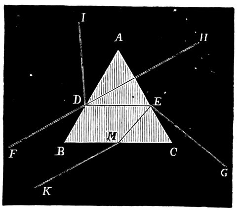
Fig. 167.—Kepler’s Diagram.
By means of a very few experiments Newton was able to show how much knowledge could be got by examination of the prism. The first proposition in Newton’s Optics is an attempt to prove that light, which differs in colour, differs also in degree of refrangibility. We shall recollect from the fifth chapter what this term means, for it was there shown that whenever a ray of light enters obliquely a medium denser than that in which it had been travelling, it is bent towards the perpendicular to the surface, in fact it is refracted, 388and those rays which are most refracted by the same substance with the same angle are said to be more refrangible than others. Newton’s experiment was very simple. He took a piece of paper, one half of which was coloured red and the other half blue; and this was placed on a stand horizontally, in the light from a window, with a prism between it and the eye.
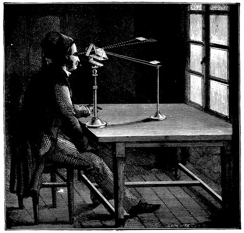
Fig. 168.—Newton’s Experiment showing the different Refrangibilities of Colours.
He went on to show, that when he allowed the beam of sunlight to fall upon the paper, strongly illuminating 389the red and blue portions, making at the same time all the rest of the room as dark as possible (so that the operation was not impeded by extraneous light), when he held a prism in a particular way, he found that the red and the blue occupied different positions when looked at through the prism. When the prism is held as shown, the red is seen below and the blue above. If the prism be turned with the refracting edge downwards, the red is seen above and the blue below. When the refracting edge is upwards, it is very clear that if the violet is seen uppermost it must be because the violet ray is more refracted, and when the red ray is uppermost, with the refracting edge of the prism downwards, it is because the red ray is the least refracted.
There are other experiments to which he alludes, and by which Sir Isaac Newton considered he had proved that lights which differ in colour differ also in degrees of refrangibility.
Newton at one step went to the sun, and his second theorem is “The light of the sun consists of rays of different refrangibility,” and then he enters into the proof by experiment. The light from the sun passes through a hole in the window-shutter and through the prism which throws a spectrum on a screen. We now see the full meaning of the different degrees of refrangibility. There he had a long band of light of all colours, the red at one end and the blue at the other, showing that the different colours are unequally refracted, or turned from their course. In this way Sir Isaac Newton determined whether the law, that light which differed in colour differed also in refrangibility, held true with regard to the sun; and he clearly showed that in this case also the light differs in refrangibility, in exactly the same way as 390the red light and the blue light had done in his experiment with the pieces of paper. He was soon able to prove to himself that the circular aperture was not the best thing he could use, because in the spectrum he had a circle of colour representing every ray into which the light could be broken up. If we put a bit of red glass in the path of the rays we get an image of the hole in red; if we use other coloured glasses, we have a circle for each particular colour; all these images overlap, and the sum total gives us an extremely mixed spectrum, something quite different from what is seen when we introduce a slight alteration, which curiously enough was delayed for a great many years.
Sir Isaac Newton recognised the difficulties there were in getting a pure spectrum by means of a circular aperture, but although he used afterwards an oblong opening instead of a circular aperture, in which we had something more or less like what we now use, namely, a “slit”—a narrow line of light; he does not seem to have grasped the point of the thing, because in one of his theorems he says he also tried triangular openings. We shall show how important it is that we should not only have an oblong opening as proposed by Newton, but that that oblong opening should be of small breadth.
The moment we exchange the circular aperture for the oblong opening of Newton, we get a spectrum of greater purity, and, as in the case of the circular opening the purity depended on the size of the circle, so also in the case of the oblong opening the purity of the spectrum depends very much on the breadth of the oblong opening.
We thus sort out the red, orange, yellow, green, blue, and violet; they are no longer mixed as they are 391when we employ a circular opening. If we attempt the same experiment with red glass interposed we get something more decided than before; we have no longer a circular patch of light, but an oblong one in the red; in fact, the exact form of the aperture, or slit, through which we have allowed the light to pass through the prism and lens to form an image.
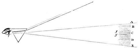
Fig. 169.—Wollaston’s first Observation of the Lines in the Solar Spectrum.
Now although Newton made these important observations on sunlight, he missed one of the things, in fact we may say the thing, which has made sunlight and starlight of so much importance to Astronomy. The oblong opening which Newton used varied from one-tenth to one-twentieth of an inch in width; but Dr. Wollaston in 1812—we had to wait from 1672 till 1812 to get this apparently ridiculously small extension—used such a narrow slit as we have mentioned, and he found that when he examined the light of the sun with a prism before the eye, he got results of which Newton had never dreamt.
Dr. Wollaston not only found the light of the sun differing in refrangibility; but in the different colours of the solar light he found a number of dark lines, which are represented by the black lines across the spectrum in Fig. 169.
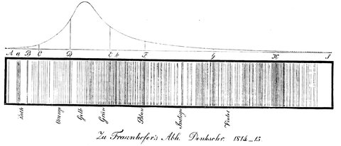
Fig. 170.—Copy of Fraunhofer’s first Map of the Lines in the Solar Spectrum.
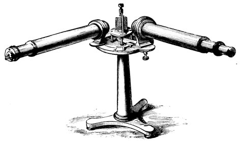
Fig. 171.—Student’s Spectroscope.
In the year 1814 Fraunhofer examined the spectrum by means of the telescope of a theodolite, directing it towards a distant slit, with a prism interposed. In this manner he observed and mapped 576 lines, the appearance of the spectrum to him being represented in Fig. 170. From this time they were called the “Fraunhofer lines.” It need scarcely be said that from the time of Wollaston until a few years ago these strange mysterious lines were a source of wonder to all observers who attempted to attack the problem. The difference between the simple prism and slit which Newton, Wollaston, and Fraunhofer used to map these lines, and the modern spectroscope, as used with or without the telescope, is due to a suggestion of Mr. Simms in 1830.
Let us refer to a modern spectroscope. Fig. 171 represents a form usually used for chemical analysis. The only difference between the spectroscope and the simple prism in Newton’s experiment is this, that in the one case the light falls directly from the slit through the 394prism on a screen and is viewed there; and in the other the eye is placed where the screen is, and looks through the prism and certain lenses at the slit.
The great improvement which Mr. Simms suggested was this simple one. He said, “It would surely be better that the light which passes through the prism or prisms independently of the number I use, should, if possible, pass through them as a parallel beam of light; and therefore, instead of putting the slit merely on one side of a prism and the eye on the other, I will, between the slit and the prism, insert an object-glass,” as shown in Fig. 172; so that the slit of the spectroscope is the representative of the hole in the shutter.
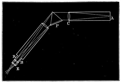
Fig. 172.—Section of a Spectroscope, showing the Path of the Ray from the Slit.
The slit is exactly in the focus of the little object-glass, C, or collimating lens, as it is called; so that naturally the light is grasped by this lens, and comes out in a parallel beam, and travels among the prism or prisms, quite irrespective of course of their number. This parallel beam, in order to be utilized by the eye after it has passed through the system of prisms, is again taken 395up by another object-glass and reduced from its parallel state into a state of convergence, and brought to a focus which can be examined by means of an eyepiece.
The red rays from the slit come to a focus at R, and the blue at B, forming there their respective images of the slit, and between B and R are a number of other images of the slit, painted in every colour that is illuminating it, thus forming a spectrum which is viewed by the eyepiece. In fact, the object-glass and eyepiece constitute a telescope, through which the slit is viewed, and the collimating lens makes the light parallel, just as if it had come from a distant object, and fit to be utilized in the telescope. This is the principle to be observed in the construction of every spectroscope.
We have now given an idea of the general nature of the instrument depending on this important addition made by Mr. Simms, which is the basis of the modern spectroscope, and it is obvious that if we want considerable dispersion, we can either increase the number of prisms, or increase their dispersive power.
We have already shown in a previous chapter that the dispersion depends on the angle of the prisms, and that the calculations necessary for making the object-glass of a telescope were based upon an observation made by passing light through a prism of a particular angle made of the same glass as that of which the proposed object-glass was to be constructed. Then, again, we took the opportunity of showing that with very dense substances greater dispersion could be obtained. We showed how the prism of dense flint glass overpowered the dispersion of the prism of the crown glass, and how the combination gave us refraction without dispersion.
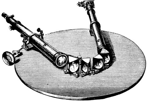
Fig. 173.—Spectroscope with Four Prisms.
Fig. 173 is a drawing of a spectroscope containing four prisms. It is a representation of that used by Bunsen and Kirchhoff when they made their maps of the solar spectrum: it is so arranged that the light after passing through the slit goes through the collimating lens, and then through the prisms; it is afterwards caught by the telescope lens and brought to a focus in front of the eyepiece. It is very important, when we have many prisms, to be able to arrange them so that whether we use one part of the spectrum or the other, each prism shall be in the best condition for allowing the light to traverse it; that is to say, that it shall be in the position of minimum deviation, when the angles of incidence and emergence are equal, and each surface refracts the ray equally. They can be arranged so, that as the telescope is moved to observe a new part of the spectrum, every prism will be automatically adjusted.
397To insure this the prisms are united to form a chain so that they all move together, and each has a radial bar to a central pin which keeps them at the proper angle.
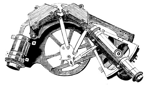
Fig. 174.—Automatic Spectroscope (Grubb’s form).
There is another arrangement which is very simple, in which we get the condition of minimum deviation by merely mounting the prisms on a spring, and then moving the spring with the telescope, in the same way as the telescope moves the other automatic arrangement.
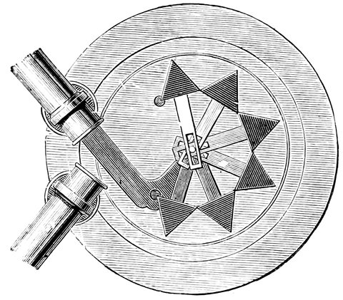
Fig. 175.—Automatic Spectroscope (Browning’s form).
For some observations, especially solar observations, 398in which the light is very intense, it is extremely important, in fact essential, to reduce the brilliancy of the spectrum; and of course this enables us, in the case of the sun especially, to increase the dispersion almost without limit, by having a great number of prisms, or even using the same twice over, in the following manner:
On the spectroscope there is a number of prisms so arranged that the light comes from the slit, and travels through the lower portion of the prisms; it then strikes against the internal reflecting surface of a right-angled prism at the back of the last prism, Fig. 176, and is sent, up to another reflecting surface, and then comes back again through the same prisms along an upper storey, and then is caught by means of a telescope above the collimator, on the slit of which the sun’s image is allowed to fall.
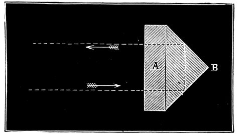
Fig. 176.—Last Prism of Train for returning the Rays.
This contrivance, suggested by the author and Prof. Young independently, is now largely used. Fig. 177 shows an ordinary spectroscope so armed. The light from the slit traverses the upper portions of the prisms; it is then thrown down by the reflecting prism seen behind the collimator, then, returning along the lower part, it is 399received by a right-angled prism in front of the object-glass of the observing telescope.
Instead of the rays of light being reflected back through the upper storey of the prisms, another method has been adopted; the last prism is in this case a half prism, and the last surface on which the rays of light fall is silvered; the rays then are returned on themselves, and, when the instrument is adjusted, come to a focus on the inside of the slit plate, forming there a spectrum, any part of which can, by moving the prisms, be made to fall on a small diagonal reflecting prism on one side of the slit, by which it is reflected to the eyepiece. In this arrangement the collimating lens becomes its own telescope lens on the return of the ray.
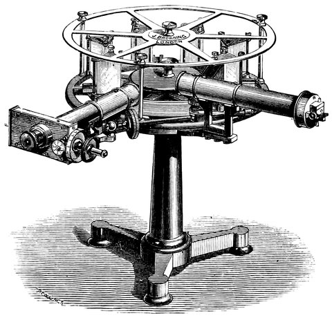
Fig. 177.—Spectroscope with returning Beam.
There is another form of spectroscope, called the direct 400vision, which is largely used for pocket instruments. The principle of it is that the light passing through it is dispersed but not turned from its course, just the reverse of the achromatic combination of the object-glass; a crown-glass prism is cemented on a flint one of sufficient angle that their deviative powers reverse each other but leave a certain portion of the flint-glass dispersion uncorrected; since, however, the dispersive power of the flint-glass is to a great extent neutralized, therefore, in order to make the instrument as powerful as one of the ordinary construction, a number of flint-glass prisms are combined with crown-glass ones, as shown in Fig. 178.

Fig. 178.—Direct Vision Prism.
There is another form of direct-vision prism, called the Herschel-Browning, in which the ray is caused to take its original course on emerging by means of two internal reflections.
We have next to say something about the principles on which the use of the spectroscope depends; if we look through one we can readily observe how each particular ray of light paints an image of the slit. Thus, if we are dealing with a red ray of light, that ray, after passing through the prisms, will paint a red image of the slit; if the light be violet, the ray will paint a violet image of the slit, and these images will be separated, because one colour is refracted more than the other. Now it follows from this that when the slit is illuminated by white light, white light being white because it contains all colours, we get an infinite number of images of slits touching or overlapping each other, and forming what is called a continuous spectrum.
Hence it is that if we examine the light of a match or candle, or even the electric light, we get such a continuous spectrum, because these light sources emit rays of every refrangibility. Modern science teaches us that they do so because the molecules—the vibrations of which produce, through the intermediary of the ether, 402the sensation of light on our optic nerve—are of a certain complexity.
In the preceding list of light sources the sun was not mentioned, because its light when examined by Wollaston and Fraunhofer, was found to be discontinuous. Now it is clear that if in a beam of light there be no light of certain particular colours, of course we shall not find the image of the slit painted at all in the corresponding regions of the spectrum. This is the whole story of the black lines in the spectrum of the sun and in the spectra of the stars.
Here and there in the spectrum of these there are colours, or refrangibilities, of light which are not represented in light which comes from those bodies, and therefore there is nothing to paint the image of the slit in that particular part of the spectrum; we get what we call a dark line, which is the absence of the power of painting an image.
But then it may be asked, How comes it that the prism and the spectroscope are so useful to astronomers? In answer we may say, that if we knew no more about the black lines in the spectra of the sun and stars than we knew forty years ago, the spectroscope ought still to be an astronomical instrument, because it is our duty to observe every fact in nature, even if we cannot explain it. But these dark lines have been explained, and it is the very explanation of them, and the flood of knowledge which has been acquired in the search after the explanation, which makes the spectroscope one of the most valuable of astronomical instruments.
Many of us are aware of the magnificent generalizations by which our countrymen, Professors Stokes and Balfour Stewart, and Ångström, Kirchhoff and Bunsen, 403were enabled to explain those wonderful lines in the solar spectrum.
These lines in the solar spectrum are there because something is at work cutting out those rays of light which are wanting, and they explained this want by showing to us that around the sun and all the stars there are absorbing atmospheres containing the vapours of certain substances cooler than the interior of the sun or of the stars.
These philosophers also showed us, that we can divide radiation and absorption into four classes, and that we can have general radiation and selective radiation, and general absorption and selective absorption, so that the phenomena that we see in our chemical and physical laboratories and our observatories may all be classed as general and selective radiation, or general and selective absorption.
Let us explain these terms more fully. Kirchhoff showed us that from incandescent solid and liquid bodies we get a continuous spectrum; thus from the carbon poles of an electric lamp we get a complete spectrum. That is called a continuous spectrum, and it is an instance of continuous radiation, which we get from the molecular complexity of solids or liquids, and likewise, from dense gases or vapours. When we examine vapours or gases which are not very dense we get an indication of selective radiation—that is to say, the light one gets from these substances, instead of being spread broadcast from the red to the violet, will simply fall here and there on the spectrum; in the case of one vapour we may get a yellow line—a yellow image of the slit—and in the case of another vapour, we may get a green one; the light selects its point of appearance, and does not appear all along the spectrum.
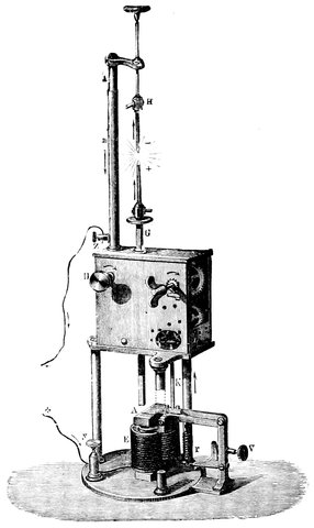
Fig. 179.—Electric Lamp. y, z, wires connecting battery of 50 Grove or Bunsen elements; G, H, carbon holders; K, rod, which stops a clockwork movement, which when going makes the poles approach until the current passes; A, armature of a magnet which by means of K frees the clockwork when not in contact; E, electro-magnet round which the current passes when the poles are at the proper distance apart, causing it to attract the armature A.
This selective radiation is due to a simplification of the molecular structure of the vapours, the simpler states are less rich in vibrations, and therefore instead of getting rays of all refrangibilities we only get rays of some.
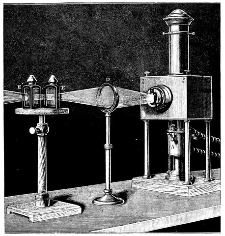
Fig. 180.—Electric Lamp arranged for throwing a spectrum on a screen. D, lens; E E´, bisulphide of carbon prisms.
Very striking experiments showing the spectra of bodies may be made with an electric lamp armed with a condenser and a narrow slit; by means of a lens this slit is magnified on a screen. Then one or two prisms of glass containing bisulphide of carbon are placed in the beam after it has traversed the lens, which draw out the image of the slit into a spectrum. We can then place a piece of sodium on the lower carbon 406pole, and when the poles are brought together it will be volatilized, and its vapour rendered luminous. Its spectrum on the screen will be seen to consist of four lines only, the yellow line being for more brilliant than the rest. Sodium was selected on account of the simplicity of its spectrum.
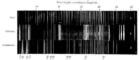
Fig. 181.—Comparison of the line spectra of Iron, Calcium, and Aluminium, with Common Impurities. Copy of a photograph, in which by dividing the slit of the spectroscope into sections, and admitting light from the various light sources through them in succession, spectra of different elements are recorded on the same photographic plate.
407If we put another metal, say calcium, in the place of the sodium, there will appear on the screen the characteristic lines of that metal. A number of distinct images of the slit in different colours is seen; if we are well acquainted with the spectrum of any metal, and see it with the spectroscope, it is easy to at once recognise it. Fig. 181 shows at one glance the spectra (1) of iron, (2) of calcium, and (3) of aluminium; and will clearly indicate the great difference there is between the radiation spectra of the rare vapours of each of the metallic elements.
Fig. 182.—Coloured Flame of Salts in the flame of a Bunsen’s Burner.
408The electric light is only required where great brilliancy is essential, as for showing spectra on a screen. A Bunsen’s burner is the best instrument for studying the spectra of metallic salts. By its means the nature of a salt can be easily studied with a hand spectroscope, and in this way an almost infinitesimal quantity can be detected.
These are instances of selective radiation. We will now turn to absorption. If we first get a continuous spectrum from our lantern and then interpose substances in the path of the beam, we can examine their effects on the light. If we first use a piece of neutral-tinted glass, which is a representative of a great many substances which do, for stopping light, what solids and liquids do for giving light—namely, it cuts off a portion of every colour; the spectrum on the screen will be dimmed; here we have a case of general absorption. If, instead of this, we hold in the beam a vessel containing magenta, a dark band in the spectrum is seen, and if we put a test-tube in its place containing iodine vapour, a number of well-defined lines pervading the spectrum is observed. In these cases clearly, the magenta in one case, and the iodine vapour in the other, have cut off certain colours, and so the slit is not painted in these colours, and dark lines or bands appear. These are instances of selective absorption, certain rays are selected and absorbed, while others pass on unheeded. The easiest method of performing these absorption experiments in the case of liquids is to place the substance in a test-tube in front of the slit of the spectroscope, as shown in Fig. 183, and point the collimator to a strong light.
Besides the absorption by liquids, the vapours of the 409metals also absorb selectively, and if a tube containing a piece of sodium and filled with hydrogen (so that the metal will not get oxidized) is placed in the path of the rays, and the sodium heated, the spectrum is at first unaffected, but as the sodium gets hot and its vapour comes off, we can mark its effect on the spectrum. We see a dark line beginning to appear in the yellow, finally the whole light of that particular colour is absorbed, and we have a dark line in its place. To sum up then:—
We get from solids, when heated, general radiation, and when they act as absorbers, we get general absorption; from gases and vapours we get selective radiation and selective absorption.
Fig. 183.—Spectroscope arranged for showing Absorption.
Now it at once strikes any one performing these experiments that the dark line of yellow sodium appears in the same place in the spectrum as the bright one, and this is so. When the absorption by sodium vapour is examined by the spectroscope, it is then seen to 410consist of two well-defined lines close together, and when the radiation is examined, it is found to consist of two bright ones, and the absorption and radiation lines, the dark and bright ones, are found to exactly agree in position in the spectrum, showing that the substance that emits a certain light is able to absorb that same light, so that it matters not whether a body is acting as an absorber or radiator, for still we recognize its characteristic lines. In 1814 Fraunhofer strongly suspected the coincidence of the two bright sodium lines with the dark lines in the sun; afterwards Brewster, Foucault, and Miller showed clearly the absolute coincidence; and Professor Stokes in 1852 came to the conclusion that the double line D, whether bright or dark, belonged to the metal sodium, and that it absorbed from light passing through it the very same rays which it is able, when incandescent, to emit. The phenomena rendered visible to us by the spectroscope have their origin, as we have said, in molecular vibration, and the reason of the identical position of the light and dark lines, and indeed the whole theory of spectrum analysis, may be shortly stated as follows:—
The spectroscope tells us that when we break a mass of matter down to its finest particles, or, as some people prefer to call them, ultimate molecules, the vibrations of these ultimate parts of each different kind of matter are absolutely distinct; so that if we get the ultimate particle, say of calcium, and observe its vibrations we find that the kind of vibration or unrest of one substance—of the calcium, for instance—is different from the kind of unrest or mode of vibration—which is the same thing—of another substance, let us say sodium. Mark well the expression, ultimate molecule, because the vibrations 411of the larger molecular aggregations are absolutely powerless to tell us anything about their chemical nature. When we bring down a substance to its finest state, and observe, by means of the prism, the vibrations it communicates to the ether, we find that, using a slit in the spectroscope and making these vibrations paint different images of the slit, we get at once just as distinct a series of images of the slit for each substance as we should get a distinct sequence of notes if we were playing different tunes on a piano.
Next, this important consideration comes into play—whenever any element finds itself in this state of fineness, and therefore competent to give rise to these phenomena, it will give rise to them in different degrees according to certain conditions. The intensest form is observed when we employ electricity. In a great many cases the vibrations may be rendered very intense by heat. The heat of a furnace or of gas will, for instance, in a great many cases, suffice to give us these phenomena; but to see them in all their magnificence—their most extreme cases—we want the highest possible temperatures, or better still, the most extreme electric energy. What we get is the vibration of these particles rendered visible to our eye by the bright images of the slit or by their bright “lines.”
But that is not the only means we have of studying these states of unrest. We can study them almost equally well if, instead of dealing with the radiation of light from the particles themselves, we interpose them between us and a light source of more complicated molecular structure, and hotter or more violently excited than the particles themselves. From such a source the light would come to us absolutely complete; that is 412to say, a perfectly complete gamut of waves of light, from extreme red to extreme violet. When we deal with these particles between us and a light-source competent to give us a continuous spectrum, then we find that the functions of these molecules are still the same, but that their effect upon our retinas is different. They are not vibrating strongly enough to give us effectively light of their own, but they are eager to vibrate, and, being so, they are employed, so to speak, in absorbing the light which otherwise would come to our eyes. So that whether we observe the bright spectrum of calcium or any other metal, or the absorption spectrum under the conditions above stated, we get lines exactly in the same part of the chromatic gamut, with the difference that when we are dealing with radiation we get bright lines, and when dealing with absorption we get dark ones.
It was such considerations as these by which the presence of sodium was determined in the sun. Soon followed the discovery of coincidence of other dark lines with the bright lines of numbers of our elements, and we had maps made by Kirchhoff, and Bunsen, and Ångström, in which almost every dark line is mapped with the greatest accuracy.
The dark lines in the spectra of the stars, and the light ones in nebulæ, comets, and meteorites have also yielded to us a knowledge more or less accurate of the elements of which these celestial bodies are built up.
These radiations and absorptions are the A B C of spectrum analysis, and they have their application in every part of the heavens which the astronomer studies with the spectroscope. But although it is the A B C it is not quite the whole alphabet. After Kirchhoff and Bunsen had made their experiments showing that we 413might differentiate between solids, liquids, gases, and vapours, by means of their spectra, and say, here we have such a substance, and there another, either by its spectrum when it is incandescent or from the absorption lines produced by it on a continuous spectrum when it is absorbing, Plücker and Hittorf showed that not only were the spectra very different among themselves, but there were certain conditions under which the spectrum of the same substance was not always the same; and although they did not make out clearly what it was, they showed that it depended either on the pressure of the gas or vapour, or the density, or the temperature. And other observations since then indicate that we get changes in spectra which are due to pressure, and not to temperature per se; so that we have another line of research opened to us by the fact, that not only are the spectra of different substances different, but that the spectra of the same substances are different under different conditions.

Fig. 184.—Geissler’s Tube.
Fig. 184 represents a hydrogen tube, called a Geissler’s tube—a glass tube with hydrogen in it and two platinum wires, one passing into each bulb, by which a current of electricity can be passed through the gas. In this case we use hydrogen gas in a state of extreme tenuity. If now one of these tubes be connected with a Sprengel pump, we can alter the condition of tenuity at pleasure, 414either reducing the contents of the tube or increasing them by admitting hydrogen from a receiver, by a tap connected to the tubing of the air-pump; we can thus considerably increase the amount of gas in the tube and bring it to something like atmospheric pressure. We shall find the colour of the gas through which the spark passes varies considerably as we increase the pressure of the hydrogen in the tube. The hydrogen at starting is nearly as rare as it can be, and if more hydrogen be let in we shall see a change of colour from greenish white to red; the hydrogen admitted has increased the pressure and the colour of the spark is entirely changed. It is a very brilliant red colour, the colour of the prominences round the sun.
It may be asked, probably, whether there are any applications of this experiment to astronomical observation. It is of importance to the astronomer to get the differences of the spectra of the same substance under different conditions, and it is found as important to get these differences between the spectra of the same substance, as those between the spectra of different substances.
There is another experiment which will show another outcome of this kind of research. Change of colour in the spark is accompanied by a considerable difference in the spectrum—that is to say, it is clear, to refer back to the colour of the hydrogen when the light was green, that we should get some green in the spectrum, and when the light became red, there would be some change or increase of light towards the red end of the spectrum. We see that that is perfectly true; but there is not only a change produced by the different pressures, as shown by the different colours; 415but if we carry the analysis still further—if, instead of dealing with the whole of the spectrum, we examine particular lines, we find in some cases that there are very great changes in them. If, for instance, we examine the bluish-green line given by hydrogen, we shall find it increase in width as the pressure increases. This kind of effect can be shown on the screen by means of the electric lamp. We place some sodium on the carbon poles in the lamp, and have an arrangement by which we can use either twenty or fifty cells at pleasure. The action of a number of cells upon the vapour of sodium in the lamp is this: the more cells we work with, the greater is the quantity of the sodium vapour thrown out, and associated with the greater quantity of vapour is a distinct variation of the light—in fact, an increase in the width and brightness of the yellow lines on the screen.
Fig. 185.—Spectrum of Sun-Spot.
Now just to give an illustration of the profitable application of this: we know, for instance, from other sources, strengthened by this, that in certain regions of the sun, called sun-spots, there are greater quantities of sodium vapour present than in others, or it exists there at greater pressure. If that be so, we ought to get the same sort of result from the sun as we get on the screen 416by varying the density of the sodium vapour. That is so. We do get changes exactly similar to the changes on the screen, only of course it is the dark lines we see, and not the bright ones: the dark lines of sodium are widened out over a sun-spot, Fig. 185, showing its presence in greater quantity, or at greater pressure.
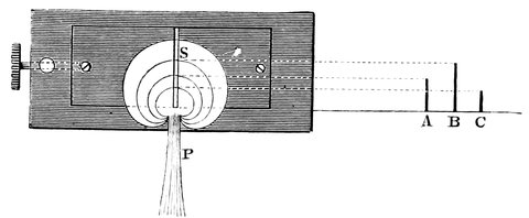
Fig. 186.—Diagram explaining Long and Short Lines.
Besides the widening of the lines due to pressure, there is something else which must be mentioned. While experimenting with the spark taken between two magnesium wires focussed on the slit of the spectroscope by a lens, the lines due to the metal were found to be of unequal lengths. Now, as the lines are simply images of the slit, the lengths of the lines depend on the length of the slit illuminated, so that in this case it appeared that the slit was not illuminated to an equal extent by all the colours given out by magnesium vapour, but that the vapour existed in layers round the wires, the lower ones giving more colours, and so also more lines, than the upper ones further from the wire, as is represented in Fig. 186; this is only meant to give an idea of the thing, and is not, of course, exactly what is seen. S is the slit of the spectroscope, P the image of one of the magnesium poles; the other, being at some little distance 417away, does not throw its image on the slit, and therefore does not interfere. The circles shown are intended to represent the layers of vapour giving out the spectrum; on the right the lower layers give A, B, and C, the next A and B, and the upper ones only B. Now we may reason from this that the layers next the poles are denser than those further off, and give a more complicated spectrum than the others; and also, if the quantity of vapour of any metal is small, we may only get just these longest lines.
Of late, experiments have been made in England on other metals—for instance, aluminium and zinc, and their compounds; and it is found that, when the vapour is diluted, as it were, one gets only the longest line or lines; and in the compounds, where the bands due to the compound compose the chief part of the spectrum, the longest line or lines of the metal only appear. Now what is the application of this? In the sun are found some of the dark lines of certain metals, but not all; for instance, there are two lines in the solar spectrum corresponding to zinc, but there are twenty-seven bright lines from the metal when volatilized by the electric spark. Why should not these also have their corresponding dark lines in the sun? The answer is, that the non-corresponding lines of the metal are the short ones, and only exist close to the metal where the vapour is dense; and in the sun the density is not sufficient to give these lines. Here, then, we have at once a means of measuring the quantity of vapour of certain metals composing the sun. It was thought that aluminium was not in the sun, as only two lines of the metal out of fourteen corresponded to black lines in the solar spectrum. It is now known that these two are the longest 418lines, and that aluminium probably exists in the sun, and zinc, strontium, and barium must also be added. These probably exist in small quantities, insufficiently dense to give all the lines seen from a spark in the air.

Fig. 187.—Comparison of the Absorption Spectrum of the Sun with the Radiation Spectra of Iron and Calcium, with Common Impurities.
419There is also another quite distinct line of inquiry in which the spectroscope helps us.
Imagine yourself in a ship at anchor, and the waves passing you, you can count the number per minute; now let the vessel move in the direction whence the waves come, you would then meet more waves per minute than before; and if the vessel goes the other way, less will pass you, and by counting the increase or decrease in the number passing, you might estimate the rates at which you were moving. Again, suppose some moving object causes ripples on some smooth water, and you count the number per minute reaching you, then if that object approach you, still moving, and so producing waves at the same rate, the number of ripples a minute will increase, and they will be of course closer together; for as the object is approaching you, every subsequent ripple is started, not from the same place as the preceding one, but a little nearer to you, and also nearer to the one preceding, on whose heels it will follow closer. By the increase in the number of ripples, and also the decrease in the distance between them, one can estimate the rate of motion of the object producing them, for the decrease in distance between the ripples is just the distance the object travels in the time occupied between the production of two waves, which was ascertained when the object was stationary.
Now let us apply this reasoning to light. Light, we 420now hold, is due to a state of vibration of the particles of an invisible ether, or extremely rare fluid, pervading all space; and the waves of light, although infinitesimally small, move among these particles.
Now we know that it is the length of the waves of light which determines their refrangibility or colour, and therefore anything that increases or diminishes their length alters their place in the spectrum; and as waves of water are altered by the body producing them moving to or from the observer, so the waves of light are changed by the motion of the luminous body; and this change of refrangibility is detected with the spectroscope. By measuring the wave-length of let us say the F line, and the new wave-length as shown by the changed position, we can estimate the velocity at which the light source is approaching or receding from us.
This application, as we shall see in the next chapter, enables us to determine the rate at which movements take place in the solar atmosphere. It also gives us the power of measuring the third co-ordinate of the motion of stars. We can, by the examination of their positions, measure the motion at right angles to our line of sight, and so determine their motion with reference to the two co-ordinates, R.A. and Dec., or Lat. and Long., and just in the same way as we can measure the velocity of the solar gases to or from us, so we can measure the motion of the stars to or from us, thereby giving us the third co-ordinate of motion.
It need scarcely be said that by the introduction of the spectroscope a new method of observation, and a new power of gaining facts, has dawned, and the sooner it is used all over the world with the enormous instruments 421which are required, the better it will be for science.
These then are some of the chief points of spectroscopic theory which makes the spectroscope one of the most powerful instruments of research in the hands of the modern astronomer.
We have now to speak of the methods of using these spectroscopes for the purpose of astronomical observations. For a certain class of observations of the sun no telescope is necessary, but some special arrangements have to be made.
Thus while Dr. Wollaston and Fraunhofer were contented with simple prisms, when Kirchhoff observed the solar spectrum, and made his careful maps of the lines, he used an instrument like Fig. 173, and for the purpose of comparing the spectrum of the sun with that of each of the chemical elements in turn, he used a small reflecting prism, covering one-half of the slit, Fig. 188, so that any light thrown sideways on to the slit would be caught by this prism, and reflected on to the slit as if it came from an object near the source of light at which the spectroscope is pointing, so that one-half of the slit can be illuminated by the sun, while the other is illuminated by another light; and on looking through the eyepiece one sees the two spectra, one above the other; so that we are able to compare the lines in the two spectra.
423The sunlight, whether coming from the sun itself or a bright cloud, is reflected, into the comparison prism, Fig. 189, of the spectroscope. An instrument called a heliostat can be used for this, reflecting the light either directly into the prism or through the medium of other reflectors.
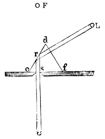
Fig. 188.—Comparison Prism, showing the path of the Ray.
The heliostat is a mirror, mounted on an axis, which moves at the same rate as the sun appears to travel, so that wherever the sun is, the reflector, once adjusted, automatically throws the beam into the instrument, so that the light of the moving sun can be observed without moving the spectroscope.
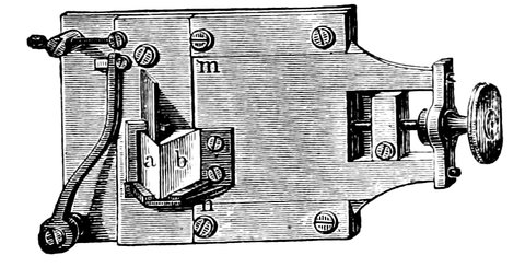
Fig. 189.—Comparison Prism fixed in the Slit.
An average solar spectrum is thus obtained, and, by means of a prism over one-half of the slit, it was quite possible for Kirchhoff and Bunsen to throw in a spectrum from any other source for comparison, and so they 424compared the spectra of the metals and other elements with the solar spectrum, and tested every line they could find in the spectra. They first found that the two lines of sodium corresponded with the two lines called D in the spectrum, then that the 460 lines of iron corresponded in the main with dark lines in the solar spectrum; and so they went on.
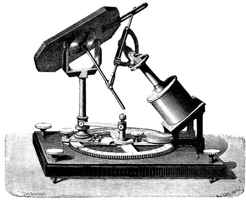
Fig. 190.—Foucault’s Heliostat.
There is, however, a method of varying the attack on this body altogether, by means of the spectroscope and telescope. We saw that Kirchhoff and Bunsen contented themselves with an average spectrum of the sun—that is to say, they dealt with the general spectrum 425which they got from the general surface of the sun, or reflected from a cloud or any other portion of the sky to which they might direct the reflector; but by means of some such an arrangement as is shown in Fig. 192, we can arrange our spectroscope so that we shall be able to form an image of the sun by the object-glass of a telescope, on the slit, and allow it to be immersed in any portion of the sun’s image we may choose. We then have a delicate means of testing what are the spectroscopic conditions of the spots and of those brighter portions of the sun which are called faculæ, and the like. And it is known that, by an arrangement of this kind, it is even possible to pick up, without an eclipse, those strange things which are called the red prominences, or the red flames, which have been seen from time to time during eclipses.
If we wish to observe any of the other celestial bodies, we must employ a telescope and form an image on the slit, or else use the heavenly body itself as a slit. In the former case spectroscopes must be attached to telescopes, and hence again they must be light and small, unless a siderostat is employed.
In the latter case the prism is placed outside the object-glass, and the true telescope becomes the observing telescope.
Fraunhofer, at the beginning of the present century, was the first to observe the spectra of the stars by placing a large prism outside the object-glass, three or four inches in diameter, of his telescope, and so virtually making the star itself the slit of the spectroscope; and in fact he almost anticipated the arrangement of Mr. Simms, and satisfied the conditions of the problem. The parallel light from the star passed through the prism, 426and by means of the object-glass was brought to a focus in front of the eyepiece, so that the spectrum of the star was seen in the place of the star itself.
This system has recently been re-invented, and the accompanying woodcut, Fig. 191, shows a prism arranged to be placed in front of an object-glass of four inches aperture. It is seen that the angle of the prism is very small. The objection to this method of procedure is that the telescope has to be pointed away from the object at an angle depending upon the angle of the prism.
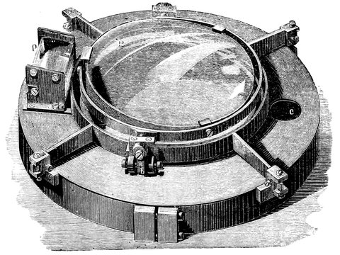
Fig. 191.—Object-glass Prism.
In the other arrangement we have the thing managed in a different way: we have the object-glass collecting the light from the star and bringing it to a focus on the slit, and it then passes on to the prisms, through which the light has to pass before it comes to the eye. In this combination of telescope and spectroscope we have what has been called the telespectroscope; one 427method of combination is seen in the accompanying drawing of the spectroscope attached to Mr. Newall’s great refractor; but any method will do which unites rigidity with lightness and allows the whole instrument to be rotated with smoothness.
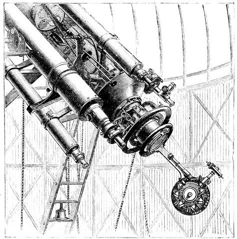
Fig. 192.—The Eyepiece End of the Newall Refractor (of 25 inches aperture), with Spectroscope attached.
For solar observation, as there is light enough to admit of great dispersion, many prisms are employed, as shown in Fig. 192; or the prisms may be made so tall that the light may be sent backwards and forwards many times by means of return prisms, to which reference has been already made.
For the observation of those bodies which give a small 428amount of light, fewer prisms must be used, and arrangements are made for the employment of reference spectra, i.e., to throw the light coming from different chemical elements into the spectroscope, in order that we may test the lines; whether any line of Sirius, for instance, is due to the vapour of magnesium, as Kirchhoff tested whether any line in the sunlight was referable to iron or the other vapours which he subsequently studied.
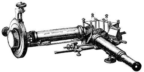
Fig. 193.—Solar Spectroscope (Browning’s form).
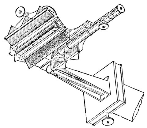
Fig. 194.—Solar Spectroscope (Grubb’s form).
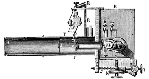
Fig. 195.—Side view of Spectroscope, showing the arrangement by which the light from a spark is thrown into the instrument by means of the reflecting prism, e, by a mirror F. (Huggins.)
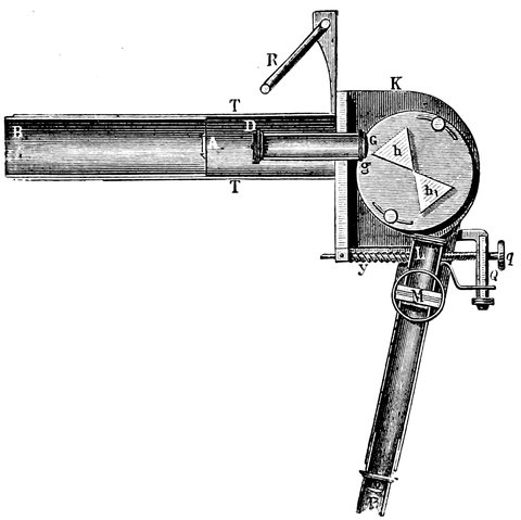
Fig. 196.—Plan of Spectroscope. T, eyepiece end of telescope, B interior tube, carrying A, cylindrical lens; D, slit of spectroscope; G, collimating lens; h h, prisms; Q, micrometer. (Huggins.)
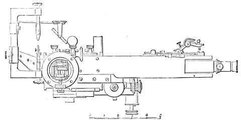
Fig. 197.—Cambridge Star Spectroscope Elevation.
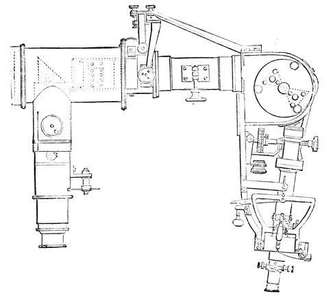
Fig. 198.—Cambridge Spectroscope Plan.
These are shown in Fig. 195. e is a reflecting prism, and F is another movable reflector to reflect the light from a spark passed between two wires of the metal to be compared, and to throw it on the prism, which reflects the light through the slit of the spectroscope to the prisms and eye; if the instrument were in perfect adjustment and turned on a star, and a person were to place his eye to the spectroscope, he would see in one-half of the field of view the spectrum of the star with 431dark lines, and in the other half the spectrum of the vapour with its bright lines; and if he found the bright lines of the vapour to correspond with any particular dark line of the spectrum of the star, he would know whether the metal exists at that star or not; so this little mechanical arrangement at once tells him what there is at the star, whether it be iron or anything else.
In Figs. 197 and 198 is shown another form of stellar spectroscope, that of the Cambridge (U.S.) observatory; it is the same in principle as that just described.
A direct vision star spectroscope is shown in Fig. 199.

Fig. 199.—Direct-vision Star Spectroscope. (Secchi.)
A new optical contrivance altogether has to be used when star spectra are observed.
The image of a star is a point, and if focussed on the slit will of course give only an extremely narrow spectrum; to obviate this a cylindrical lens is employed, which may be placed either before the slit or between the eyepiece and the eye. If placed before the slit, it draws out the image of the star to a fine line which just fits the slit, so that a sufficient portion of the slit is illuminated to give a spectrum wide enough to show the lines, or the slit may be dispensed with altogether.
432In stellar observations, when the cylindrical lens is used in front of the slit, special precautions should be taken so as to secure that the position of the cylindrical lens and slit in which the spectrum appears brightest should be used. In any but the largest telescopes the spectra of the stars are so dim that unless great care is used the finer lines will be missed. A slit is not at all necessary for merely seeing the spectra; indeed they are best seen without one. If a slit be used, it should lie in a parallel and not in a meridian; under these circumstances slight variations in the rate of the clock are of no moment.
In this and in other observational matters it is good to know what to look for, and there are great generic differences between the spectra of the various stars. In Fig. 200 are represented spectra from the observations of Father Secchi. In the spectrum of Sirius, a representative of Type I., very few lines are represented, but the lines are very thick; and stars of this class are the easiest to observe.
Next we have the solar spectrum, which is a representative of Type II., one in which more lines are represented. In Type III. fluted spaces begin to appear; and in Type IV., which is that of the red stars, nothing but fluted spaces is visible, and this spectrum shows that there is something different at work in the atmosphere of those red stars to what there is in the simpler atmosphere of the first—of Type I. These observations were first attempted, and carried on with some success, by Fraunhofer, and we know with what skill and perseverance Mr. Huggins has continued the work in later years, even employing reference spectra and determining their chemical constitution as well as their class.
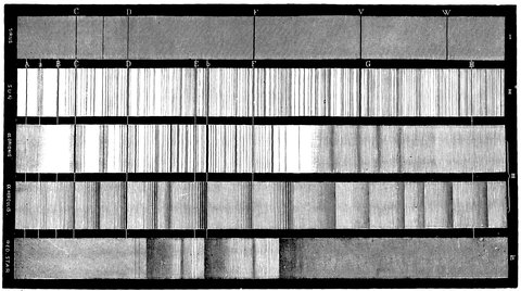
Fig. 200.—Types of Stellar Spectra (Secchi).
We need scarcely say that the same arrangement, 434minus the cylindrical lens, is good for observing the nebulæ and such other celestial objects as comets and planets.
For all spectrum work, it has to be borne in mind that the best definition is to be had when the actual colour under examination is focussed on the slit. With reflectors, of course, there is no difference of focus for the different colours. As the best object-glasses are over-corrected for chromatic aberration, the red focus is generally inside and the blue one outside the visual one. It is not necessary to move the whole spectroscope to secure this; all collimators should be provided with a rack and pinion giving them a bodily movement backwards and forwards.
This precaution is of especial importance in the case of solar observations, to which we have next to refer.
If in any portion of the sun’s image on the plate carrying the slit we see a spot, all we have to do is to move the telescope, and with it of course the sun’s image, so that the slit is immersed in the image of the spot; if, however, we wish to observe a bright portion of the sun, we can immerse this slit in the bright portion. Again, if we wish to examine the chromosphere of the sun, we simply have to cover half the slit with the sun, and allow the other part of the slit to be covered by any surroundings of the sun, and, so to speak, to fish round the edge; the lower half of the slit, say, is covered by the sun itself, and therefore we shall get from that half the ordinary solar spectrum; the upper half is, however, immersed in the light reflected from our atmosphere, giving a weak solar spectrum, so that we get a bright and feeble spectrum side by side. But besides the atmospheric light falling on the upper part of the slit, the 435image of anything surrounding the sun falls there also, and its spectrum is seen with the faint solar spectrum, and we find there a spectrum of several bright lines. Now, as an increase of dispersive power will spread out a continuous spectrum and weaken it, we may almost indefinitely weaken the atmospheric spectrum, and so practically get rid of it, still leaving the bright-line spectrum with the lines still further separated; so that if it were not for our atmosphere, we should get only the spectrum of the sun and that of its surroundings; one a continuous spectrum with black lines, and the other consisting of bright lines only.
Now if we suppose these observations made—if the precaution to which we have alluded be not taken, the spectrum of the sun-spot will differ but little from that of the general surface, and the chromospheric lines will scarcely be visible.
If the precaution be taken, in the case of the spot it will be found that every one of the surrounding pores is also a spot; and if the air be pure the spectrum will be full of hard lines running along the spectrum, just like dust lines, but emphatically not dust lines, because they change with every movement of the sun. The figure of the spot spectrum on p. 415 will show what is meant. Fig. 201 will show the appearance of the chromospheric line when the blue-green light is exactly focussed; the boundary of the spectrum of the photosphere approaches in hardness that at the end of the slit.
By measuring the lengths of the lines we can estimate the height of the vapours producing them; we find from this that magnesium is usually present to a height of a few hundred miles, and that hydrogen extends to between 3,000 and 4,000 miles; in some positions of the slit the 436hydrogen lines are seen to start up to great heights, showing the presence of flames or prominences extending in height to sometimes 100,000 miles.
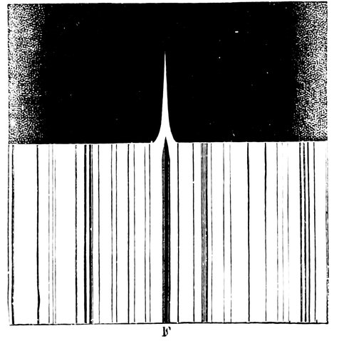
Fig. 201.—Part of Solar Spectrum near F.
If, without changing the focus, we open the slit wider, and throw the sun’s image just off the slit, so that the very bright continuous spectrum no longer dazzles the eye, we shall be able to see these flames whenever they cross the opening, for the image of the slit is focussed on the eye, and the sun and its flames are focussed on the slit, so if we virtually remove the slit by opening it wide, we see the flames; still the limit of opening is soon approached, and the flood of atmospheric light soon masks them. The red hydrogen line of the spectrum is the best for viewing them, although the yellow or blue will answer. We may also place the sun’s image so that the slit is tangential to it, in which case a greater length of the hydrogen layer, or chromosphere, as it is called, is visible, although its height is limited by the opening of the slit.
437By these means we are able to view a small part of the chromosphere at a time, and to go all round the sun in order to obtain a daily record of what is going on. If, however, we throw the image of the sun on a disc of metal of exactly the same size, we eclipse the sun, but allow the light of the chromosphere to pass the edge of the disc; this of course is masked by the atmospheric light, but if the annulus, or ring of chromosphere, be reduced sufficiently small, it can be viewed with a spectroscope in the place of a slit, in fact it is virtually a circular slit on which the chromosphere rests. By this means nearly the whole of the chromosphere can be seen at once. This is accomplished as follows:—
The image of the sun is brought to focus on a diaphragm having a circular disk of brass in the centre, of the same size as the sun’s image, so that the sun’s light is obstructed and the chromospheric light is allowed to pass. The chromosphere is afterwards brought to a focus again at the position usually occupied by the slit of the spectroscope; and in the eyepiece is seen the chromosphere in circles corresponding to the “C” or other lines.
A lens is used to reduce the size of the sun’s image, and keep it of the same size as the diaphragm at different times of the year; and other lenses are used in order to reduce the size of the annulus of light to about ⅛ inch, so that the pencils of light from either side of it may not be too divergent to pass through the prisms at the same time, in order that the image of the whole annulus may be seen at once. There are mechanical difficulties in producing a perfect annulus of the required size, so one ½ inch in diameter is used, and can be reduced virtually to any size at pleasure.
From what has been said it is easy to see that we 438really now get a new language of light altogether, and a language which requires a good deal of interpretation.
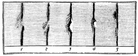
Fig. 202.—Distortions of F line on Sun.
We have still, indeed, to consider some curious observations which are now capable of being made every day when anything like a sun-storm is going on, by means of the arrangement in which the spectroscope simply deals with the light that comes from a small portion of the sun instead of from all the sun. If we make the slit travel over different portions of the sun on which any up-rushes of heated material, or down-rushes of cold material, or other changes, are going on from change of surface temperature, the Fraunhofer lines, which we have before shown to be straight, instead of being so, appear contorted and twisted in all directions. On the other hand, if we examine the chromosphere under the same conditions, we find the bright lines contorted in the same manner. The usually dark lines, moreover, sometimes appear bright, even on the sun itself; sometimes they are much changed in their relative positions with reference to the solar spectrum. The meaning of these contortions has already been hinted at (p. 420).
It was there shown that every colour, or light of every refrangibility, is placed by the prisms in its own particular position, so if a ray of light alters its position 439in the spectrum it must change its colour or refrangibility, so the light producing the F line in the one case, and the absent light producing the dark line in the other, differ slightly in colour, or are rather more or less refrangible than the normal light from hydrogen. In the case when the F line is wafted towards the blue end of the spectrum, the light falling on the slit is rather more refrangible than usual; and in the middle drawing, Fig. 203, where the F line bifurcates, the slit is supplied with two kinds of light differing slightly in refrangibility. Not only does the light radiated by a substance change in this way, but the light absorbed by that substance also changes, hence the contortions of the black lines are due to a similar cause.
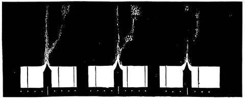
Fig. 203.—Displacement of F line on edge of Sun.
Here, therefore, we have evidence of a change of refrangibility, or colour, of the light coming from the hydrogen surrounding the sun. This change of refrangibility is due to the motion of the solar gases, as explained in the last chapter.
So we find that the hydrogen producing the light giving us one of the forms of the F line, shown in Fig. 203, is moving towards us at the rate of 120 miles a 440second, while that giving the other form is moving away from us.
Let us see how these immense velocities are estimated.
By means of careful measurements, Ångström has shown
on his map of the solar spectrum the absolute length of
the waves of light corresponding to the lines; thus the
length of the wave of light of hydrogen giving the
F line is 4860
10000000 of a millimeter. In Fig. 203 the
dots on either side of the F line show the positions,
where light would fall, if it differed from the F light by
1, 2, 3, or 4 ten-millionths of a millimeter, so that in
the figure the light of that part of the line wafted over
the fourth dot is of a wave-length of 4 ten-millionths of
a millimeter less than that of the normal F light, which
has a wave-length 4860
10000000 of a millimeter. The F light
therefore has had its wave-length reduced by 4
4860 = 1
1215
part; and in order that each wave may be decreased by
this amount, the source of the light must move towards
us with a velocity of 1
1215 of the velocity of light, which
is 186,000 miles per second, and 1
1215 of 186,000 is
about 150; this then is the velocity, in miles per second,
at which the hydrogen gas must have been moving
towards us in order to displace the light to the fourth
dot, as shown in the figure.
In previous chapters we have considered the lessons that we can learn from light—from the vibrations of the so-called ether—when we put questions to it through various instruments as interpreters. There is still another method of putting questions to these same vibrations, and the instrument we have now to consider is the Polariscope.
The spectroscope helped us to inquire into the lengths of the luminiferous waves; from the polariscope we learn whether there is any special plane in which these waves have their motion.
The polariscope is an instrument which of late years has become a useful adjunct to the telescope in examining the light from a body in order to decide whether it is reflected or not, and to ascertain indirectly the plane in which the rays reflected to the eye lie. The action of the instrument depends upon the fact that light which consists solely of vibrations perpendicular to a given plane is said to be completely polarized in that plane. Light that contains an excess of vibrations perpendicular to a given plane is said to be partially polarized in that plane.
442It was Huyghens that discovered the action of Iceland spar in doubly refracting light; and the light which passed the crystal was called polarized light at the suggestion of Newton, who, it must be remembered, looked upon light as something actually emitted from luminous bodies; these projected particles were supposed, after passage through Iceland spar, to be furnished with poles analogous to the poles of a magnet, and to be unable to pass through certain bodies when the poles were not pointing in a certain direction. It was not until the year 1808 that Malus discovered the phenomenon of polarization by reflection. He was looking through a double-refracting prism at the windows of the Luxembourg Palace, on which were falling the rays of the setting sun. On turning the prism he noticed the ordinary and extraordinary images alternately become bright and dark. This phenomenon he at once saw was in close analogy to that which is observed when light is passed through Iceland spar. At first he thought it was the air that polarized the light, but subsequent experiments showed him that it was due to reflection from the glass.
Let us examine some of the phenomena before we proceed to show the use astronomers make of them.
It is the property of some crystals, such as tourmaline, when cut parallel to a given direction, called the optic axis of the crystal, to absorb all vibrations or resolved parts of vibrations perpendicular to this line, transmitting only vibrations parallel to it.
A similar absorption of vibrations perpendicular to a given direction may be effected by various other combinations, of which one, Nicol’s prism, is in most common use. Any of these arrangements may be used 443as an analyzer with the telescope, for determining whether the light is completely or partially polarized, and in either of these cases which is the plane of polarization. The plane containing the direction of the rays and the line in the analyzer to which the transmitted vibrations are parallel, is called the plane of analyzation: all the light which reaches the eye consists of vibrations in the plane of analyzation. As we rotate the analyzer, we rotate equally the plane of analyzation. If we find a position of the plane of analyzation for which the light received by the eye is a maximum, we know that the light from the object is partially or completely polarized in a plane perpendicular to the plane of analyzation when in this position. To determine whether the polarization is partial or complete, we must turn the analyzer through an angle of 90° from this position: if we now obtain complete darkness, we know that there are no vibrations having a resolved part parallel to the plane of analyzation in this position, or that the light is completely polarized in this plane: if there be still some light visible, the polarization is only partial.
To explain this a little more fully, we may compare the vibrations or waves of light to waves of more material things: we may have the vibrating particles of the ether moving up and down as the particles do in the case of a wave of water, or the particles may move horizontally as a snake does in moving along the ground. We may consider that ordinary light consists of vibrations taking place in all planes, but if it passes through or is reflected by certain substances at certain angles, the vibrations in certain planes are, as it were, filtered out, leaving only vibrations in a certain plane. This light is then said to be polarized, and its plane of 444polarization is found by its power of passing through polarizing bodies only when they are in certain positions.
If, for instance, a ray of ordinary light is passed through a crystal of tourmaline, the vibrations of the filtered ray will only lie in one plane; if then a second crystal of tourmaline be held in a similar position to the first, the ray will pass through it unaffected; but if it be turned through a quarter of a circle about the ray as an axis, the ray will no longer be able to pass, for being in a position at right angles to the first, it will filter out just the rays that the first allows to pass. For illustration, take a gridiron: if we attempt to pass a number of sheets of paper held in all positions through it, only those in a certain plane, viz., that of the rods forming the gridiron, could be passed through, and those that would go through would also go through any number of gridirons held in a similar position. But if another gridiron be placed so that its bars cross those of the first, the sheets of paper could no longer pass, and it is evident that if we could not see or feel the paper, we could tell in what plane it was by the position in which the gridiron must be held to let it pass, and having found the paper to be, say horizontal, we know that the bars of the first gridiron are also horizontal. So with light, we can analyze a ray of polarized light and say in what plane it is polarized.
The example of the gridiron, however, does not quite represent the action of the second crystal; for if the bars of the second gridiron are turned a very small distance out of coincidence with those of the first, the sheets of paper would be stopped; but with light, the intensity of the ray is only gradually diminished, until 445it is finally quenched when the axes of the crystals are at right angles to each other.
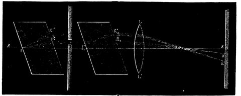
Fig. 204.—Diagram showing the Path of the Ordinary and Extraordinary Ray in Crystals of Iceland Spar.
Light is polarized by transmission and by reflection. We have already, when we were discussing the principle involved in the double-image micrometer, seen how a crystal of Iceland spar divides a ray into two parts at the point of incidence. Now these two rays are oppositely polarized, that is to say, the vibrations take place in planes perpendicular to each other; the vibrations of the incident light in one plane are refracted more than the vibrations in the opposite plane, and we have therefore two rays, one called the ordinary ray, and the other the extraordinary ray. Fig. 204 shows a ray of light, S I, incident on the first crystal at I; it is then divided up into the ordinary ray I R and the extraordinary one I R´; a screen is then interposed, stopping the extraordinary ray and allowing the ordinary one to fall on the second crystal at I. If then this crystal be in a similar position to the first, this ray, vibrating only in one plane, will pass onwards as an ordinary ray, I R; there being no vibrations in the perpendicular plane to form an extraordinary ray, there will be only one circle 446of light thrown on the screen at O by the lens. But, if the second crystal be turned round the line S S as an axis, the plane of vibration of the ray falling on its surface will no longer coincide with the plane in which an ordinary ray vibrates in the crystal, and it therefore becomes split up into two, one vibrating in the plane as an ordinary ray, and the other in that of an extraordinary ray; we have therefore the ray I R´ in addition to the first, and consequently a second circle on the screen at E´. As the crystal rotates, the plane of extraordinary refraction becomes more and more coincident with the plane of vibration of the incident ray, until, when it has revolved through 90°, it coincides with it exactly; it then passes through totally as an extraordinary ray, and as the refractive power of the crystal is greater for vibrations in this plane, we get all the light traversing the direction I R and falling on the screen at E´, and there being then no light ordinarily refracted, the circle O disappears. Fig. 205 shows the relative brightness of the circles E and O as they revolve round the centre S of the screen, the images produced by the ordinary and the extraordinary ray becoming alternately bright and dark as the crystal is rotated. Fig. 206 shows the images on the screen when the ordinary ray is stopped by the first screen instead of the extraordinary one.
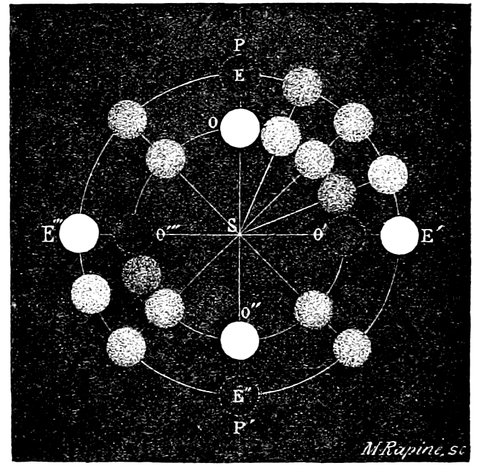
Fig. 205.—Appearance of the Spots of Light on the Screen shown in the preceding Figure, allowing the ordinary ray to pass and rotating the second Crystal.
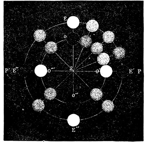
Fig. 206.—Appearance of Spots of Light on Screen on rotating the second Crystal, when the extraordinary ray is allowed to pass through the first Screen.
A crystal of tourmaline acts in a like manner to Iceland spar, but the ordinary ray is rapidly absorbed by the crystal, so that the extraordinary ray only passes. There is an objection to the use of it, as it is not very transparent, and a Nicol’s prism is now generally used for polarizing light. It is constructed out of a rhombo-hedron of Iceland spar cut into two parts in a plane passing through the obtuse angles, and the two halves are then joined by Canada balsam. The principle of construction is this: the power of refracting light possessed by Canada balsam is less than that possessed by Iceland spar for the ordinary ray, and greater in the case of the extraordinary ray; in consequence, the ordinary ray is reflected at the surface of junction, while 448the extraordinary ray passes onwards through the crystal.
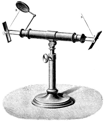
Fig. 207.—Instrument for showing Polarization by Reflection.
It is manifest then that if two Nicols are used instead of two simple crystals, represented in Fig. 204, there will be only one spot of light on the screen, which is due to the extraordinary ray, and as in certain positions this no longer passes (for the ordinary ray, which appears in the place of the extraordinary when the crystal is used, cannot pass through the Nicol), no light 449at all passes in such positions, so that we can use the second Nicol as an analyzer to ascertain in what plane the light is polarized.
Light is also polarized by reflection from the surface of a transparent medium. When a ray of ordinary light falls on a plate of glass at an angle of 54° 55´ with the normal, the reflected ray is perfectly polarized, and at other inclinations the polarization is incomplete. Here then is polarization by reflection. Fig. 207 shows an apparatus for producing this phenomenon. The light foiling on the first mirror from E is reflected through the tube as a polarized beam, and this is analyzed by the other mirror (I), whose plane can be rotated round the axis of the tube. The angle of polarization differs with different substances according to their refractive power, for polarization of the reflected ray is perfect only when the angle of incidence is such that the reflected ray is at right angles to the refracted one.
As a result of what we have said, the light of the sun reflected from the surface of water or from the glass of a window is polarized, and although it may be dazzling to the eye, it is reduced, or even entirely cut off, when falling at the polarizing angle, by looking through the transparent Nicol’s prism or plate of glass held in certain positions and acting as an analyzer. On rotating the analyzer there is an alternation of intensity, and by looking at the window through a crystal of Iceland spar as an analyzer, two images would be seen which would alternate in brightness as the crystal is rotated. So also there is a difference in the intensity of the light from the sky when the analyzer is rotated, showing that the light reflected from the watery and dust particles in the air is polarized, and by the position of the analyzer we find 450that it is polarized in the plane we should expect if it be, as it is, reflected from the sun.
It will be asked, however, what is the astronomical use of determining whether light has an excess of vibrations in any given direction?
To this we may reply that light that is reflected from any body is generally partially polarized in the plane of reflection, and that if we find that the light received from any body is partially polarized in a given plane, we may conclude that it has very likely been reflected in that plane.
Hence then in the case of any celestial body the origin of the light of which is doubtful, the polariscope tells us whether the light is intrinsic or reflected.
It tells us more than this, it tells us the plane in which the reflection has taken place. As the polarization takes place, when it does take place, at the celestial body, all we have to do is to attach an analyzer to the telescope.
A careful application of the above principles has shown that the light from the sun’s corona is partially polarized, and in the same plane as it would be if reflected from small particles in the neighbourhood of the sun: so also a portion of the light of Coggia’s Comet was found to be polarized, and therefore we say that it reflected sunlight in addition to its own proper light.
In what has been hitherto said we have only considered the use of a Nicol, or glass plates, or crystal of Iceland spar as an analyzer, and by the variation of brightness the presence and plane of polarization have been determined; but unless the polarization is somewhat decided, it could not be detected by this method. Advantage is therefore taken of the fact that a plate of 451quartz rotates the plane of polarization of a ray passing through it, and it rotates the more refrangible colours more than the others, and some crystals rotate the plane one way, and others in the opposite direction: the crystals are therefore called respectively right- and left-handed quartz; the thicker the quartz the greater the angle through which the plane of polarization is twisted.
This supplies us with a most delicate apparatus, which we next describe. A crystal of right- and a crystal of left-handed quartz are taken and cut to such thickness that a ray of any colour, say green, has its plane turned through 90° on passing through each of them. They are then cut into the form of a semicircle and placed side by side. Any change of the angle of polarization will now affect each plate differently. In one plate the colours will change from red to violet, in the other from violet to red.
If now a ray of polarized light, say vibrating in a vertical plane, falls on them, the green rays will have their plane of vibration turned through 90° by each crystal, and the vibration of the green from both crystals will then be in the horizontal plane. Nicol’s prism interposed between the quartz plates and the eye, so as to allow horizontal vibrations to pass, will show the green from both crystals of equal intensity; the rays of other colours, being turned through a greater or less angle than 90°, will not be vibrating horizontally, and will therefore only partially pass through, so green will be the prevailing colour. If now the plane of vibration of the original ray be turned a little out of the vertical, the ray, on the red side of the green, will appear in one half, and that on the violet side of the green in the other: so that immediately the plane of 452polarization changes, the plates transmit a different colour, and the apparatus must be twisted round through just the same angle as the polarized ray in order to get the crystals of the same colour. It is therefore obvious that the angle made by a polarized ray with a fixed plane is easily ascertained in this manner.
There is also another instrument for detecting polarization which is perhaps more commonly used than the biquartz: it is generally called Savart’s analyser, and is extremely sensitive in its action. On looking through it at any object emitting ordinary light, the white circle of light limited by the aperture of the instrument only is seen; but if any polarized light should happen to be present, a number of parallel bands, each shaded from red to violet, make their appearance; on rotating the instrument a point is found when a very slight motion causes the bands to vanish and others to appear in the intermediate spaces, and knowing the position required for the change of bands with light polarized in a known plane, say the vertical plane, it is easy to find how far the plane of polarization of any ray is from the vertical, by the number of degrees through which the instrument must be turned to change the bands. The construction of the instrument, and especially its action, is not easy to understand without a considerable knowledge of optics, but it may be stated that a plate of quartz is cut, in a direction inclined at 45° to its axis, into two parts of the same thickness; one part is then turned through a right angle and placed with the same surfaces in contact as before; these are fixed in the instrument so that the light shall traverse them perpendicularly to the plane of section; the light then passes through a Nicol’s prism as an analyser to the eye. The lines observed, “black 453centred” in one position, and “white centred” in the position at right angles to this, are always in the direction before referred to. The delicacy of the test supplied by this arrangement increases as this direction is more nearly parallel or perpendicular to the plane of polarization of the ray under examination.
We come now last of all to that branch of the work of the physical astronomer which bids fair in the future to replace all existing methods of observation.
In the introductory chapter we referred to the introduction of photographic records of astronomical phenomena as marking an epoch in the development of the science. In the last ones we have to dwell briefly on the modus operandi of the various methods by which the eye is thus being gradually replaced.
The point of celestial photography is that it not only enables us to determine form and place, absolutely irrespective of personal equation so far as the eye is concerned, but that, properly done, it gives us a faithful and lasting record of the operation, so that it is not forgotten; Mr. De La Rue has called the photographic plate the retina which does not forget, and an excellent name it is.
We may pass over altogether the ordinary photographic processes, which have been carried on with a degree of skill and patience which is beyond all praise, and confine our attention exclusively to the instrumental processes. Be it remembered, we have no longer to 455consider the visual rays, but the so-called chemical rays, which lie at the violet end of the spectrum.
We must also recollect that, in a former chapter, we have seen that the optician’s business was to throw aside the violet rays altogether—to discard them, caring nothing for them, because, so far as the visible form of the objects is concerned, they help very little. But we shall see in a moment that, if we wish to use refractors for photographing, we must abolish this idea, and undo everything we did to get a perfect telescope to see the body, because in the case of the photographic processes employed at present, the visible rays have as little to do with building up the image on the photographic plate as the blue rays have to do with building up the image on the retina of the eye. We shall see presently how admirably this has been done by Mr. Rutherfurd. If, however, we use reflectors instead of refractors, we are able to utilize all the rays by means of the same mirror without alteration, as the focus is the same for all rays, so that a reflector is equally good for all classes of observation.
Let us first consider the cases in which the plate is made to replace the retina with the ordinary telescope. We shall see in the sequel that whether the spectroscope, polariscope, or other physical instrument be added to the telescope—when we pass, that is to say, from mechanical to physical astronomy—the plate can still replace the eye with advantage.
The body of the telescope, with the object-glass or mirror at one end and the plate at its focus in place of the eyepiece, forms the camera, corresponding to those we find in photographic studies. The plate-holder shown in section in the accompanying figure is therefore the 456only addition required to make a telescope into a camera for ordinary work. Fig. 208.
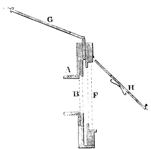
Fig. 208.—Section of Plate-holder.
A is a screw of such a size that it can be inserted into the eyepiece end of the telescope; the sensitive plate is held between a lid at the back, which opens for the plate to be inserted, and a slide in front, which is drawn out so as to expose the face of the plate to the object. A piece of ground glass of extreme fineness is inserted in the slide, on which the object is focussed before the sensitive plate is put in. It is easy then by the eyepiece focussing-screw to put this nearer or further away from the object-glass, so that the image is thrown sharply on the ground glass. When that is done the ground glass is taken away, and the sensitive plate put there in its place, and then exposed as required, so that the methods are similar to the ordinary photographic process.
We have here an arrangement that enables us to photograph the moon, stars, and planets. M. Faye has proposed that for the transit circle also the photographic method should be applied, the chronograph registering 457the time of the instantaneous opening of the slide, instead of the time the star is seen to transit, so that the position of the star with respect to the wires is registered at a certain known time; therefore, not only for physical astronomy have we the means of making observations without an observer at all, but also for position observations.
Every one knows sufficient of photography to be aware that, if we wish to secure the image of a faint object, such as a faint star or a faint part of the moon, we must expose the plate for some little time, as we have to do in ordinary photography if the day is dull, and therefore the larger the aperture of the telescope the more light passes; and the shorter the focus is, and the more rapid the process, the shorter will be the exposure; if the focus is short, the image will be small; but as we can magnify the image afterwards, rapidity becomes of greater moment, as the shorter the time of exposure is the less atmospheric and other disturbances and errors in driving the telescope come into play. Still, if we photograph the moon or other object, we do not wish to limit ourselves to the size of the original negative obtained at the focus. If the negative is well defined—that is, if it possesses the quality of enlargeableness—there is no difficulty in getting enlarged prints.
The method of enlarging photographs is very simple; all that is required is a large camera, the negative to be copied being placed nearer the lens than the prepared paper, so that the image is larger than the original. Fig. 209 shows an enlarging camera: the body, A, can be made of wood, or better still, of a soft material, bellows-fashion, so that the length can be altered at pleasure. In the end, at B, is fixed a lens—an ordinary 458portrait lens will do, but a proper copying lens is preferable; and E is a piece of wood with a hole in its centre, over which the negative is placed, the distance of E to B being also adjustible; then, by altering the lengths of B E and B C, the image of the negative can be made to appear of suitable size. At the end, C, a piece of sensitive paper is placed, and the light of the sun being allowed to fall through the negative and lens, the paper soon becomes printed, and can be toned and fixed as an ordinary paper positive. The camera may be carried on a rough equatorial mounting, consisting of an axis pointing to the pole, and pulled round with the sun by attaching a string to an equatorial telescope, moved by clockwork; or a heliostat can be used with more advantage, thereby allowing the camera to be stationary; a good enlarging lens is a very desirable thing, for most lenses seem to distort the image considerably.
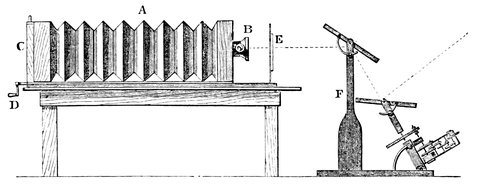
Fig. 209.—Enlarging Camera. F, heliostat for throwing beam of sunlight on the reflector, which throws it into the camera; E, negative; B, focussing-lens; C, plate- or paper-holder; D, focussing-screw.
If we wish to obtain a large direct image of the moon, we must, as said before, employ a telescope of as long a focal length as possible; for reasons just 459mentioned, this is not always desirable. If, however, large images can be obtained as good as small ones, they can of course be enlarged to a much greater size. The primary image of the moon taken by Mr. De La Rue’s exquisite reflector is not quite an inch in diameter. In one of Mr. Rutherfurd’s telescopes of fifteen feet focus, the image of the moon is somewhat larger—about one and a half inch in diameter. In Mr. Newall’s magnificent refractor, the focal length of which is thirty feet, the diameter is over three inches. In the Melbourne reflector the image obtained is larger still.
In celestial photography we have not only to deal with faint objects. With the sun the difficulty is of no ordinary character in the opposite direction, because the light is so powerful that we have to get rid of it. Now there are two methods of doing this, and as in a faint object we get more light by increasing the aperture, so with a bright light like that of the sun we can get rid of a large amount of it by reducing the aperture of our telescope; but it is found better to reduce infinitesimally the time of exposure, and methods have been adopted by which that has been brought down to the one-hundredth part of a second.
Let us show the simple way in which this can be done by the means of an addition to an ordinary plate-holder.
Fig. 208 shows the ordinary plate-holder, like those used generally for photography. What is termed the instantaneous slide, B, Fig. 210, consists of a plate with an adjustible slit in it inserted between the object itself and the focus. This can be drawn rapidly across the path of the rays by means of a spring, D; we can bring it to one side, and fix it by a piece of cotton, E, and 460then we can release it by burning the cotton, when the spring draws it rapidly across. The velocity of the rush of the aperture across the plate, and the time of exposure, can be determined by the strength of the spring and the aperture of the slit. If the velocity is too great, we can alter the size of the slit, C. If we absorb some of the superabundant light by means of yellow glass, or some similar material, we can keep the opening wide enough to prevent any bad effects of diffraction coming into play.
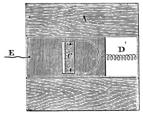
Fig. 210.—Instantaneous Shutter.
The light of the sun is so intense that another method
may be employed. Instead of having the plate at the
focus of the object-glass we may introduce a secondary
magnifier in the telescope itself, and thus obtain an
enlarged image, the time necessary for its production
being still so short (1
50th of a second) that nothing is lost
from the disturbances of the air.
A telescope with this addition is called a photoheliograph. The first instrument of this kind was devised by Mr. De La Rue, and for many years was regularly employed in taking photographs of the sun at Kew.
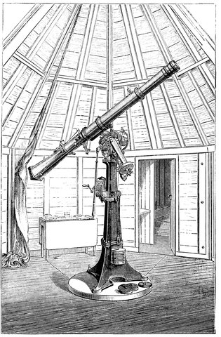
Fig. 211.—Photoheliograph as erected in a Temporary Observatory for Photographing the Transit of Venus in 1874.
Some astronomers object to this secondary magnifier, and to obtain large images use very long focal lengths, and of course a siderostat is employed. In this way Professor Winlock obtained photographs of the sun which have surpassed the limits of Mr. Newall’s refractor; 462the negatives have a good definition, and show a considerable amount of detail about the spots; they were taken by a lens, inserted at the end of a gas-pipe forty feet long. The pipe was fixed in a horizontal position, facing the north, and at the extreme north part of it was the lens, a single one of crown glass, with no attempt to correct it. In front of it was a siderostat, moved by a clock, reflecting the light down the tube, so that the image of the sun could be focussed on the ground glass at the opposite end.
One will see the importance of shortening the time for even the brightest object. Those who are favoured with many opportunities of looking through large telescopes know that the great difficulty we have to deal with is the atmosphere; because we have to wait for definition, and the sum total of the photograph of any one particular thing depends upon these atmospheric fits. If we require to photograph an object, it will be obvious that the more fits we have, the worse it will be, because we get a number of images partially superposed which would otherwise give as good an effect as we could get by an ordinary eye observation. It is therefore most important to reduce the interval as much as possible.
The process used should therefore be the most rapid attainable; any work on photography will give a number of processes of different degrees of rapidity, but a process that suits one person’s manipulation may prove a failure in another’s, and the general principles are the only rules suitable for all. First, the glass plate should be carefully cleaned, the collodion lightly coloured, the bath strong and neutral, certainly not acid, and the developer fairly strong. Pyrogallic acid and silver should not be used for intensifying; a good intensifier is made by adding to a solution of iodide of potassium, strength one grain to the ounce of water, a saturated solution of bichloride of mercury, drop by drop, until the precipitate at first formed ceases to be re-dissolved; use this after fixing.
Now let us inquire what has been done by this important adjunct to ordinary means of observing. We may say that celestial photography was founded in the year 1850 by Professor Bond, who obtained a daguerreotype of the moon about that date. An immense advance has been made, but not so great as there might have 464been if the true importance of the method had been recognized as it ought to have been; and if we study the history of the subject we find that till within the last few years we have to limit ourselves to the works of two men who, after Bond, set the work rolling. Several observers took it up for a time; but the work requires much both of time and money, and different men dropped off from time to time. There remained always steadfast one Englishman and one American—Mr. De La Rue and Mr. Rutherfurd. The magnificent work Mr. De La Rue has done was begun in 1852. He was so anxious to see whether England could not do something similar to what had been done in America, that, without waiting for a driving clock, he thought he would see whether photographs of the moon could be taken by moving the telescope by hand. He soon found that he was working against nature—that nature refused to be wooed in this way; the moon in quite a decided manner declined to be photographed, and we waited five years till Mr. De La Rue was armed with a perfect driving clock. Mr. Rutherfurd was waiting for the same thing in America.
At last, in 1857, Mr. De La Rue got a driving clock to his reflector of thirteen inches aperture, and began those admirable photographs of the moon which are now so well known. Since the above date the moon has been photographed times without number, and Mr. De La Rue has made a series which shows the moon in all her different phases. They are remarkable for the beautiful way in which the details come out in all parts of the surface. We must recollect that these pictures of which we have spoken, some of them a yard in diameter, were first taken on glass about three inches across, the 465image covering the central inch. At the same time the British Association granted funds for the photographic registration of sun-spots at the Kew Observatory, where the sun was photographed every day for many years.
Encouraged by success, Mr. De La Rue, in 1858, attacked the planets Jupiter and Saturn, and some of the stars. He discovered that photographs of the moon can be combined in the stereoscope so that the moon shows itself perfectly globular.
To accomplish this result it was necessary to photograph her at different epochs, so that the libration, which gives it the appearance of being turned round slightly and looking as it would do to a person several thousand miles to the right or left of the telescope, should be utilized. These two views when combined give the appearance of solidity just as the image of a near object combined by the two eyes gives that appearance. The reason of this appearance of solidity is easily seen by looking at an orange or ball first with one eye and then with the other, when it is noticed that each eye sees a little more of one side than the other; and it is the combination of these slightly dissimilar images that gives the solid appearance.
If we examine two of these photographs combined for the stereoscope, we see that they have the appearance of being taken from two stations a long distance apart. One shows a little more of the surface on one side than the other. They are obtained in different lunations, when the moon, in the same phase, has turned herself slightly round, showing more of one side. In this way we have a distinct effect due to libration. In the year 1859 Mr. De La Rue found that sun-pictures could be combined stereoscopically in the same manner.
466When we turn to the labours of Mr. Rutherfurd, we
find him in 1857 armed with a refractor of 11¼ inches
aperture; the actinic focus, or rather the nearest approach
to a focus, was 7
10ths of an inch from the visual focus.
With this telescope, without any correction whatever,
he, in 1857 and 1858, obtained photographs of the
moon which, when enlarged to five inches in diameter,
were well defined. He also obtained impressions of
stars down to as far as the fifth magnitude, and also of
double stars some 3˝ apart—for instance, γ Virginis was
photographed double. The ring of Saturn and belts
of Jupiter were also plainly visible, but ill-defined.
The satellites of Jupiter failed to give an image with
any exposure, while their primary did so in five or ten
seconds. The actinic rays, instead of coming to a point
and producing an image of a satellite, were spread over
a certain area and thereby rendered too weak to impress
the plate.
In the summer of 1858 Mr. Rutherfurd combined his first stereograph of the moon independently of Mr. De La Rue’s success in England.
Mr. Rutherfurd then commenced an inquiry of the greatest importance, which will in time bring about a revolution in the processes employed.
In 1859 he attempted, by placing lenses of different curvatures between the object-glass and the focus, to bring the chemical rays together, leaving the visual rays out of the question; this had the effect of shortening the focus considerably and improving the photographs; but he found that, except for the middle of the field, this method would not answer. He therefore in 1860 attempted another arrangement, and one which he found answered extremely well for short telescopes.
467Between the lenses of the object-glass of a 4½-inch refractor he put a ring which separated the lenses by three-quarters of an inch, and reduced the power of the flint-glass lens, which corrects the crown-glass for colour, so that the combination became achromatic for the violet rays instead of for the yellow. With this lens he was successful to a certain extent: he obtained even better results than with the 11¼ inch; but eventually he rejected this method, which we may add has recently been tested by M. Cornu, who thinks very highly of it.
He next attempted a silver-on-glass mirror in 1861; in the atmosphere of New York it only lasted ten days; he gave it up; and he then very bravely, in 1864, attacked the project de novo, and began an object-glass of a telescope which should be constructed so as to give best definition with the actinic rays, just as ordinary object-glasses are made to act best with the visual rays.
He found that in order to bring the actinic portion of the rays to a perfect focus, it was necessary that a given crown-glass lens should be combined with a flint, which will produce a combined focal length of about ⅒ shorter than would be required to satisfy the conditions of achromatism for the eye. This combination was of course absolutely worthless for ordinary visual observation; his new lens when finished was 11¼ inches aperture and a little less than 14 feet focal length. With this he obtained impressions of ninth magnitude stars, and within the area of a square degree in the Prœsepe in Cancer twenty-three stars were photographed in three minutes’ exposure. Castor gave a strong impression in one second, and stars of 2˝ distance showed as double. But even with this method Mr. Rutherfurd was not satisfied. Coming back to the 11¼-inch object-glass 468which he had used at first, he determined to see whether or not the addition of a meniscus lens outside the front lens would not give him the requisite shortness of the focus and bring the actinic rays absolutely together. By this arrangement he got a telescope which can be used for all purposes of astronomical research, and he has also eclipsed all his former photographic efforts.
Having in the previous chapter dealt with some of the pioneer work, we come finally to consider some of the applications which in the last years have occupied most attention.
With regard to the sun, we need scarcely say that Messrs. De La Rue and Stewart have been enabled, by the photographic method, to give us data of a most remarkable character, showing the periodicity of the changes on the sun’s surface, and so establishing their correlation with magnetic and other physical phenomena.
These photographic researches, following upon the eye observations of Schwabe, Spörer, Carrington and others, have opened up to us a new field of inquiry in connection with the meteorology of the globe; and it is satisfactory to learn that photoheliographs are now daily at work at Greenwich, Paris, Potsdam, and the Mauritius, and that shortly India will be included in the list.
Quite recently, the importance of these permanent records of the solar surface has been demonstrated by Dr. Janssen, the distinguished director of the Physical Observatory at Meudon, in a very remarkable manner.
It seems a paradox that discoveries can be made 470depending on the appearance of the sun’s surface by observations in which the eye applied to the telescope is powerless; but this is the statement made by Dr. Janssen himself, and there is little doubt that he has proved his point.
Before we come to the discovery itself let us say a little concerning Dr. Janssen’s recent endeavours. Among the six large telescopes which now form a part of the equipment of the new Physical Observatory recently established by the French government at Meudon, in the grounds of the princely Chateau there, is one to which Dr. Janssen has recently almost exclusively confined his attention. It is a photoheliograph giving images of the sun on an enormous scale—compared with which the pictures obtained by the Kew photoheliograph are, so to speak, pigmies, while the perfection of the image and the photographic processes employed are so exquisite, that the finest mottling on the sun’s surface cannot be overlooked by those even who are profoundly ignorant of the interest which attaches to it.
This perfection of size and image have been obtained by Dr. Janssen by combining all that is best in the principles utilised in one direction by Mr. De La Rue, and in the other by Mr. Rutherfurd, to which we have before referred. In the Kew photoheliograph, which has done such noble work in its day that it will be regarded with the utmost veneration in the future, we have first a small object-glass corrected after the manner of photographic lenses, so as to make the so-called actinic and the visual rays coincide, and then the image formed by this lens is enlarged by a secondary magnifier constructed, though perhaps not too accurately, so as to make the actinic and visual rays unite in a second image on a 471prepared plate. Mr. Rutherfurd’s beautiful photographs of the sun were obtained in a somewhat different manner. In his object-glass, as we have seen, he discarded the visual rays altogether and brought only the blue rays to a focus, but when enlargements were made, an ordinary photographic lens—that is, one in which the blue and yellow rays are made to coincide—was used.
Dr. Janssen uses a secondary magnifier, but with the assistance of M. Pragmowski he has taken care that both it and the object-glass are effective only for those rays which are most strongly photographic. Nor is this all; he has not feared largely to increase the aperture and focal length, so that the total length of the Kew instrument is less than one-third of that in operation in Paris.
The largely-increased aperture which Dr. Janssen has given to his instrument is a point of great importance. In the early days of solar photography the aperture used was small, in order to prevent over-exposure. It was soon found that this small aperture, as was to be expected, produced poor images in consequence of the diffraction effects brought about by it. It then became a question of increasing the aperture while the exposure was reduced, and many forms of instantaneous shutters have been suggested with this end in view. With these, if a spring be used, the narrow slit which flashes across the beam to pay the light out into the plate changes its velocity during its passage as the tension of the spring changes. Of this again Dr. Janssen has not been unmindful, and he has invented a contrivance in which the velocity is constant during the whole length of run of the shutter.
By these various arrangements the plates have now 472been produced at Meudon of fifteen inches diameter, showing details on the sun’s surface subtending an angle of less than one second of arc.
So much for the modus operandi. Now for the branch of solar work which has been advanced.
It is more than fifteen years ago since the question of the minute structure of the solar photosphere was one of the questions of the day. The so-called “mottling” had long been observed. The keen-eyed Dawes had pointed out the thatch-like formation of the penumbra of spots, when one day Mr. Nasmyth announced the discovery that the whole sun was covered with objects resembling willow-leaves, most strangely and effectively interlaced. We may sum up the work of many careful observers since that time by stating that the mottling on the sun’s surface is due to dome-like masses, and that the “thatch” of the penumbra is due to these dome-like masses being drawn, either directly or in the manner of a cyclone, towards the centre of the spot. In fact the “pores” in the interval between the domes are so many small spots, while the faculæ are the higher levels of the cloudy surface. The fact that faculæ are so much better seen near the limb proves that the absorption of the solar atmosphere rapidly changes between the levels reached by the upper faculæ and the pores.
Thus much premised, we now come to Dr. Janssen’s discovery.
An attentive examination of his photographs shows that the surface of the photosphere has not a constitution uniform in all its parts, but that it is divided into a series of figures more or less distant from each other, and presenting a peculiar constitution. These figures have contours more or less rounded, often very rectilinear, 473and generally resembling polygons. The dimensions of these figures are very variable; they attain sometimes a minute and more in diameter.
While in the interior of the figures of which we speak the grains are clear, distinctly terminated, although of very variable size, in the boundary the grains are as if half effaced, stretched, stained; for the most part, indeed, they have disappeared to make way for trains of matter which have replaced the granulation. Everything indicates that in these spaces, as in the penumbræ of spots, the photospheric matter is submitted to violent movements which have confused the granular elements.
We have already referred to the paradox that the sun’s appearance can now be best studied without the eye applied to the telescope. This is what Dr. Janssen says on that point.
“The photospheric network cannot be discovered by optical methods applied directly to the sun. In fact, to ascertain it from the plate, it is necessary to employ glasses which enabled us to embrace a certain extent of the photographic image. Then if the magnifying power is quite suitable, if the proof is quite pure, and especially if it has received rigorously the proper exposure, it will be seen that the granulation has not everywhere the same distinctness; that the parts consisting of well-formed grains appear as currents which circulate so as to circumscribe spaces where the phenomena present the aspect we have described. But to establish this fact, it is necessary to embrace a considerable portion of the solar disc, and it is this which it is impossible to realise when we look at the sun in a very powerful instrument, the field of which is, by the very fact of its power, very small. In these conditions we may very easily conclude 474that there exist portions where the granulation ceases to be distinct or even visible; but it is impossible to suppose that this fact is connected with a general system.”
But it is not alone with the uneclipsed sun that the new method enables us to make discoveries. The extreme importance of photography in reference to eclipse observations cannot be over estimated. Most of our best observations of eclipses have been wrought by means of photography. The time of an eclipse is an exciting time to astronomers; and it is important that we should have some mechanical operation which should not fail to record it.
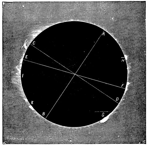
Fig. 212.—Copy of Photograph taken during the Eclipse of 1869.
The first eclipse photograph was taken in 1851. In 1860, chiefly owing to the labours of Mr. De La Rue, our 475knowledge was enormously increased. The Kew photoheliograph was the instrument used, and the series of pictures obtained showed conclusively that the prominences belonged to the sun. In 1868 the prominences were again photographed. In 1869 the Americans attacked the corona, and their suggestion that the base of it was truly solar has been confirmed by other photographs taken in 1870, 1871, and 1875. Although to the eye the phenomena changed from place to place, to the camera it was everywhere the same with the same duration of exposure.
It is not to be wondered at, then, that on the occasion of the last transit of Venus, which may be regarded as a partial eclipse of the sun, photography was suggested as a means of recording the phenomena.
Science is largely indebted to Dr. Janssen, Mr. De La Rue, and others for bringing celestial photography to aid us in this branch of work also. While on the one hand astronomers have to deal with precious moments, to do very much in very little time, in circumstances of great excitement; the photographer on the other goes on quietly preparing and exposing his plates, and noting the time of the exposure, and thus can make the whole time taken by the planet in its transit over the sun’s disc one enormous base line. His micrometrical measures of the position of the planet on the sun’s disc can be made after all is over. It was suggested by Dr. Janssen that a circular plate of sufficient size to contain sixty photographs of the limb of the sun, at the points at which Venus entered and left it could be moved on step by step round its centre, and so expose a fresh surface to the sun’s image focussed on it, say every second. In this 476way the phenomena of the transit were actually recorded at several stations.
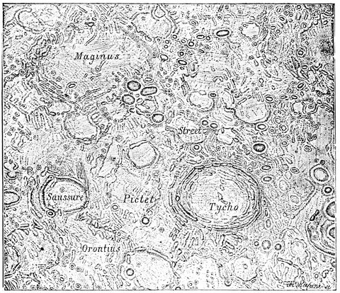
Fig. 213.—Part of Beer and Mädler’s Map of the Moon.
With reference to the moon, we have said enough to show that if we wish to map her correctly, it is now no longer necessary to depend on ordinary eye observations alone; it is perfectly clear that by means of an image of the moon, taken by photography, we are able to fix many points on the lunar surface. Still, although we can thus fix these and use them as so many points of the first order, as one might say, in a triangulation, there is much that photography cannot do; the work of the eye 477observer would be essential in filling in the details and giving the contour lines required to make a map of the moon.
The accompanying drawings on the same scale show that up to the present, for minute work, the eye beats the camera.
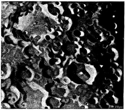
Fig. 214.—The same Region copied from a Photograph by De La Rue.
The light of the moon is so feeble in blue rays that a long exposure is necessary for a large image, and during the exposure all the errors in the rate of the clock are magnified.
We need not enlarge on the extreme importance of what Mr. Rutherfurd has been doing in photographing 478star clusters and star groups. It is doubly important to astronomy, and starts a new mode of using the equatorial and the clock; in fact, it gives us a method by which observations may be photographically made of the proper motion of stars, and even the parallax of stars may be thus determined independently of any errors of observers. Mr. Rutherfurd shows that the places of stars can be measured by a micrometer on a plate in the same way as by ordinary observation; hence photography can be made use of in the measurement of position and distance of double stars.
As an instance of the extreme beauty of the photographs of stars produced by a proper instrument, it may be stated that with the full aperture of the 11¼-inch object-glass corrected only for the ordinary rays, Mr. Rutherfurd found that he required an exposure of more than ten seconds to get an image of the bright star Castor; but now, instead of requiring ten seconds, he can get a better image in one. The reason of this is, that, with the object-glass corrected only for the visual rays, the chemical ones are spread over a certain small area instead of coming to a point, and so, of course, the intensity is reduced; but when the chemical rays all come to one point the intensity is greater, since the image of the star is smaller and the action more intense.
Let us follow Mr. Rutherfurd a little in his actual work. First, a wet plate is exposed for four minutes. This gives stars down to the tenth magnitude. But there may be points on the plate which are not stars, hence a second impression is taken on the same plate after it has been slightly moved. All points now doubled are true stars. Now for measures of arc. Another photograph is taken, and the driving clock is stopped; the now 479moving stars down to the fourth magnitude are bright enough to leave a continuous line, the length of this in a very accurately known interval, say two minutes, enables the arc to be calculated.
Next comes the mapping. The negative is fixed on a
horizontal divided circle on glass illuminated from below.
Above it is a system of two rails, along which travels a
carrier with two microscopes, magnifying fifty diameters.
By the one in the centre, with two cross wires in the field
of view, the photograph is observed; by the other, armed
with a wire micrometer, a divided scale on glass which
is fixed alongside the rail is read. Suppose we wish to
measure the distance between two stars on the plate.
The plate is rotated, so that the line which joins them
coincides with that which is described by the optical
axis of the central microscope marked by the cross wires
when the carrier runs along the rails. This microscope
is then brought successively over the two stars, and the
other microscope over the scale reads the nearest division,
while the fractions are measured by the micrometer.
Hence, then, the fixed scale, and not a micrometer screw,
is depended upon for the complete distance. In this
way the distance between the stars on the plate can be
measured to the 1
500 part of a millimetre.
So far then we have shown how photography has been called in to the aid of the astronomer, and how, by means of photography, pictures of the different celestial bodies have been obtained of surpassing excellence. Now, photography is also the handmaiden to the spectroscope in the same way as it is the handmaiden to the telescope. Not only are we able to determine and register the appearance of the moon and planets, 480but, day by day, or hour by hour, we can photograph a large portion of the solar spectrum; and not only so, but the spectrum of different portions of the sun: nay, even the prominences have been photographed in the same manner; while more recently still, Drs. Huggins and Draper have succeeded in photographing the spectrum of some of the stars. We owe the first spectrum of the sun, showing the various lines, to Becquerel and Draper; the finest hitherto published we owe to Mr. Rutherfurd.
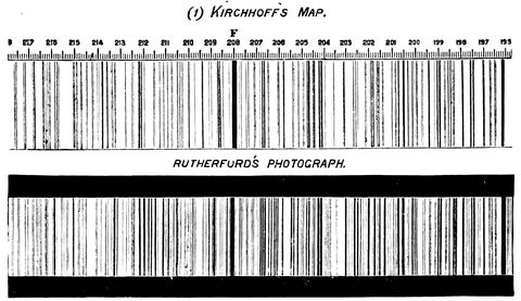
Fig. 215.—Comparison between Kirchhoff’s Map and Rutherfurd’s Photograph.
This magnificent spectrum extends from the green part of the spectrum right into that part of the spectrum called the ultra-violet. Of course it had to be put together from different pictures, because there is a different length of exposure required for the different parts; the exposure of any particular part of the spectrum must be varied according to the amount of chemical intensity in that part. If the line G was exposed, say for fifteen seconds, the spectrum near the line F would 481require to be exposed for eight minutes, and at the line H, which is further away from the luminous part of the spectrum than G, there the exposure requisite would be two or three minutes.
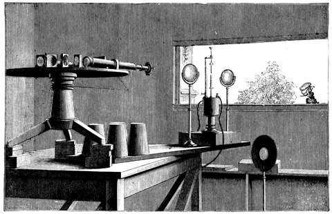
Fig. 216.—Arrangement for Photographically Determining the Coincidence of Solar and Metallic Lines.
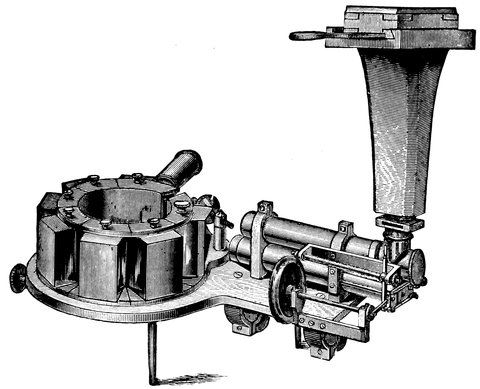
Fig. 217.—Telespectroscope with Camera for obtaining Photographs of the Solar Prominences.
In order to obtain a photograph of the average solar spectrum, the camera replaces the observing telescope, and a heliostat is used, as in the ordinary way. The beam, however, should be sent through an opera-glass in order to condense it, and thereby to render the exposure as short as possible.
Further, if an electric lamp be mounted as shown in Fig. 216, observations, similar to those originally made by Kirchhoff, of the coincidence on the various metallic 483lines with the Fraunhofer ones, can be permanently recorded on the photographic plate. The lens between the lamp and the heliostat is for the purpose of throwing an image of the sun between the carbon poles. The lens between the lamp and spectroscope then focuses both the poles and the image of the sun on to the slit. The spectrum of the sun is first obtained by uncovering a small part of the slit and allowing the image of the sun to fall on this uncovered portion, the lamp not being in action. When this has been done the light of the sun is shut off. The metal to be studied is placed in the lower pole; the adjacent portion of the slit is uncovered, that at first used being closed in the process. The current is then passed to render the metal incandescent. After the proper exposure the plate is developed and the spectra are seen side by side. Fig. 187 is a woodcut of a plate so obtained.
If the spectrum of any special part of the sun, or the prominences, has to be photographed, then either a siderostat must be employed, or a camera is adjusted to the telespectroscope, as shown in Fig. 217.
For the stars, of course, much smaller dispersion must be used, but the method is the same; and what has already been said by way of precaution about the observation of stellar spectra applies equally to the attempt to obtain spectrum photographs of these distant suns.
End of Project Gutenberg's Stargazing: Past and Present, by J. Norman Lockyer

*** END OF THIS PROJECT GUTENBERG EBOOK STARGAZING: PAST AND PRESENT ***

***** This file should be named 53172-h.htm or 53172-h.zip *****
This and all associated files of various formats will be found in:
        http://www.gutenberg.org/5/3/1/7/53172/

Produced by Richard Tonsing, Chris Curnow and the Online
Distributed Proofreading Team at http://www.pgdp.net (This
file was produced from images generously made available
by The Internet Archive)

Updated editions will replace the previous one--the old editions will
be renamed.

Creating the works from print editions not protected by U.S. copyright
law means that no one owns a United States copyright in these works,
so the Foundation (and you!) can copy and distribute it in the United
States without permission and without paying copyright
royalties. Special rules, set forth in the General Terms of Use part
of this license, apply to copying and distributing Project
Gutenberg-tm electronic works to protect the PROJECT GUTENBERG-tm
concept and trademark. Project Gutenberg is a registered trademark,
and may not be used if you charge for the eBooks, unless you receive
specific permission. If you do not charge anything for copies of this
eBook, complying with the rules is very easy. You may use this eBook
for nearly any purpose such as creation of derivative works, reports,
performances and research. They may be modified and printed and given
away--you may do practically ANYTHING in the United States with eBooks
not protected by U.S. copyright law. Redistribution is subject to the
trademark license, especially commercial redistribution.

START: FULL LICENSE

THE FULL PROJECT GUTENBERG LICENSE
PLEASE READ THIS BEFORE YOU DISTRIBUTE OR USE THIS WORK

To protect the Project Gutenberg-tm mission of promoting the free
distribution of electronic works, by using or distributing this work
(or any other work associated in any way with the phrase "Project
Gutenberg"), you agree to comply with all the terms of the Full
Project Gutenberg-tm License available with this file or online at
www.gutenberg.org/license.

Section 1. General Terms of Use and Redistributing Project
Gutenberg-tm electronic works

1.A. By reading or using any part of this Project Gutenberg-tm
electronic work, you indicate that you have read, understand, agree to
and accept all the terms of this license and intellectual property
(trademark/copyright) agreement. If you do not agree to abide by all
the terms of this agreement, you must cease using and return or
destroy all copies of Project Gutenberg-tm electronic works in your
possession. If you paid a fee for obtaining a copy of or access to a
Project Gutenberg-tm electronic work and you do not agree to be bound
by the terms of this agreement, you may obtain a refund from the
person or entity to whom you paid the fee as set forth in paragraph
1.E.8.

1.B. "Project Gutenberg" is a registered trademark. It may only be
used on or associated in any way with an electronic work by people who
agree to be bound by the terms of this agreement. There are a few
things that you can do with most Project Gutenberg-tm electronic works
even without complying with the full terms of this agreement. See
paragraph 1.C below. There are a lot of things you can do with Project
Gutenberg-tm electronic works if you follow the terms of this
agreement and help preserve free future access to Project Gutenberg-tm
electronic works. See paragraph 1.E below.

1.C. The Project Gutenberg Literary Archive Foundation ("the
Foundation" or PGLAF), owns a compilation copyright in the collection
of Project Gutenberg-tm electronic works. Nearly all the individual
works in the collection are in the public domain in the United
States. If an individual work is unprotected by copyright law in the
United States and you are located in the United States, we do not
claim a right to prevent you from copying, distributing, performing,
displaying or creating derivative works based on the work as long as
all references to Project Gutenberg are removed. Of course, we hope
that you will support the Project Gutenberg-tm mission of promoting
free access to electronic works by freely sharing Project Gutenberg-tm
works in compliance with the terms of this agreement for keeping the
Project Gutenberg-tm name associated with the work. You can easily
comply with the terms of this agreement by keeping this work in the
same format with its attached full Project Gutenberg-tm License when
you share it without charge with others.

1.D. The copyright laws of the place where you are located also govern
what you can do with this work. Copyright laws in most countries are
in a constant state of change. If you are outside the United States,
check the laws of your country in addition to the terms of this
agreement before downloading, copying, displaying, performing,
distributing or creating derivative works based on this work or any
other Project Gutenberg-tm work. The Foundation makes no
representations concerning the copyright status of any work in any
country outside the United States.

1.E. Unless you have removed all references to Project Gutenberg:

1.E.1. The following sentence, with active links to, or other
immediate access to, the full Project Gutenberg-tm License must appear
prominently whenever any copy of a Project Gutenberg-tm work (any work
on which the phrase "Project Gutenberg" appears, or with which the
phrase "Project Gutenberg" is associated) is accessed, displayed,
performed, viewed, copied or distributed:

  This eBook is for the use of anyone anywhere in the United States and
  most other parts of the world at no cost and with almost no
  restrictions whatsoever. You may copy it, give it away or re-use it
  under the terms of the Project Gutenberg License included with this
  eBook or online at www.gutenberg.org. If you are not located in the
  United States, you'll have to check the laws of the country where you
  are located before using this ebook.

1.E.2. If an individual Project Gutenberg-tm electronic work is
derived from texts not protected by U.S. copyright law (does not
contain a notice indicating that it is posted with permission of the
copyright holder), the work can be copied and distributed to anyone in
the United States without paying any fees or charges. If you are
redistributing or providing access to a work with the phrase "Project
Gutenberg" associated with or appearing on the work, you must comply
either with the requirements of paragraphs 1.E.1 through 1.E.7 or
obtain permission for the use of the work and the Project Gutenberg-tm
trademark as set forth in paragraphs 1.E.8 or 1.E.9.

1.E.3. If an individual Project Gutenberg-tm electronic work is posted
with the permission of the copyright holder, your use and distribution
must comply with both paragraphs 1.E.1 through 1.E.7 and any
additional terms imposed by the copyright holder. Additional terms
will be linked to the Project Gutenberg-tm License for all works
posted with the permission of the copyright holder found at the
beginning of this work.

1.E.4. Do not unlink or detach or remove the full Project Gutenberg-tm
License terms from this work, or any files containing a part of this
work or any other work associated with Project Gutenberg-tm.

1.E.5. Do not copy, display, perform, distribute or redistribute this
electronic work, or any part of this electronic work, without
prominently displaying the sentence set forth in paragraph 1.E.1 with
active links or immediate access to the full terms of the Project
Gutenberg-tm License.

1.E.6. You may convert to and distribute this work in any binary,
compressed, marked up, nonproprietary or proprietary form, including
any word processing or hypertext form. However, if you provide access
to or distribute copies of a Project Gutenberg-tm work in a format
other than "Plain Vanilla ASCII" or other format used in the official
version posted on the official Project Gutenberg-tm web site
(www.gutenberg.org), you must, at no additional cost, fee or expense
to the user, provide a copy, a means of exporting a copy, or a means
of obtaining a copy upon request, of the work in its original "Plain
Vanilla ASCII" or other form. Any alternate format must include the
full Project Gutenberg-tm License as specified in paragraph 1.E.1.

1.E.7. Do not charge a fee for access to, viewing, displaying,
performing, copying or distributing any Project Gutenberg-tm works
unless you comply with paragraph 1.E.8 or 1.E.9.

1.E.8. You may charge a reasonable fee for copies of or providing
access to or distributing Project Gutenberg-tm electronic works
provided that

* You pay a royalty fee of 20% of the gross profits you derive from
  the use of Project Gutenberg-tm works calculated using the method
  you already use to calculate your applicable taxes. The fee is owed
  to the owner of the Project Gutenberg-tm trademark, but he has
  agreed to donate royalties under this paragraph to the Project
  Gutenberg Literary Archive Foundation. Royalty payments must be paid
  within 60 days following each date on which you prepare (or are
  legally required to prepare) your periodic tax returns. Royalty
  payments should be clearly marked as such and sent to the Project
  Gutenberg Literary Archive Foundation at the address specified in
  Section 4, "Information about donations to the Project Gutenberg
  Literary Archive Foundation."

* You provide a full refund of any money paid by a user who notifies
  you in writing (or by e-mail) within 30 days of receipt that s/he
  does not agree to the terms of the full Project Gutenberg-tm
  License. You must require such a user to return or destroy all
  copies of the works possessed in a physical medium and discontinue
  all use of and all access to other copies of Project Gutenberg-tm
  works.

* You provide, in accordance with paragraph 1.F.3, a full refund of
  any money paid for a work or a replacement copy, if a defect in the
  electronic work is discovered and reported to you within 90 days of
  receipt of the work.

* You comply with all other terms of this agreement for free
  distribution of Project Gutenberg-tm works.

1.E.9. If you wish to charge a fee or distribute a Project
Gutenberg-tm electronic work or group of works on different terms than
are set forth in this agreement, you must obtain permission in writing
from both the Project Gutenberg Literary Archive Foundation and The
Project Gutenberg Trademark LLC, the owner of the Project Gutenberg-tm
trademark. Contact the Foundation as set forth in Section 3 below.

1.F.

1.F.1. Project Gutenberg volunteers and employees expend considerable
effort to identify, do copyright research on, transcribe and proofread
works not protected by U.S. copyright law in creating the Project
Gutenberg-tm collection. Despite these efforts, Project Gutenberg-tm
electronic works, and the medium on which they may be stored, may
contain "Defects," such as, but not limited to, incomplete, inaccurate
or corrupt data, transcription errors, a copyright or other
intellectual property infringement, a defective or damaged disk or
other medium, a computer virus, or computer codes that damage or
cannot be read by your equipment.

1.F.2. LIMITED WARRANTY, DISCLAIMER OF DAMAGES - Except for the "Right
of Replacement or Refund" described in paragraph 1.F.3, the Project
Gutenberg Literary Archive Foundation, the owner of the Project
Gutenberg-tm trademark, and any other party distributing a Project
Gutenberg-tm electronic work under this agreement, disclaim all
liability to you for damages, costs and expenses, including legal
fees. YOU AGREE THAT YOU HAVE NO REMEDIES FOR NEGLIGENCE, STRICT
LIABILITY, BREACH OF WARRANTY OR BREACH OF CONTRACT EXCEPT THOSE
PROVIDED IN PARAGRAPH 1.F.3. YOU AGREE THAT THE FOUNDATION, THE
TRADEMARK OWNER, AND ANY DISTRIBUTOR UNDER THIS AGREEMENT WILL NOT BE
LIABLE TO YOU FOR ACTUAL, DIRECT, INDIRECT, CONSEQUENTIAL, PUNITIVE OR
INCIDENTAL DAMAGES EVEN IF YOU GIVE NOTICE OF THE POSSIBILITY OF SUCH
DAMAGE.

1.F.3. LIMITED RIGHT OF REPLACEMENT OR REFUND - If you discover a
defect in this electronic work within 90 days of receiving it, you can
receive a refund of the money (if any) you paid for it by sending a
written explanation to the person you received the work from. If you
received the work on a physical medium, you must return the medium
with your written explanation. The person or entity that provided you
with the defective work may elect to provide a replacement copy in
lieu of a refund. If you received the work electronically, the person
or entity providing it to you may choose to give you a second
opportunity to receive the work electronically in lieu of a refund. If
the second copy is also defective, you may demand a refund in writing
without further opportunities to fix the problem.

1.F.4. Except for the limited right of replacement or refund set forth
in paragraph 1.F.3, this work is provided to you 'AS-IS', WITH NO
OTHER WARRANTIES OF ANY KIND, EXPRESS OR IMPLIED, INCLUDING BUT NOT
LIMITED TO WARRANTIES OF MERCHANTABILITY OR FITNESS FOR ANY PURPOSE.

1.F.5. Some states do not allow disclaimers of certain implied
warranties or the exclusion or limitation of certain types of
damages. If any disclaimer or limitation set forth in this agreement
violates the law of the state applicable to this agreement, the
agreement shall be interpreted to make the maximum disclaimer or
limitation permitted by the applicable state law. The invalidity or
unenforceability of any provision of this agreement shall not void the
remaining provisions.

1.F.6. INDEMNITY - You agree to indemnify and hold the Foundation, the
trademark owner, any agent or employee of the Foundation, anyone
providing copies of Project Gutenberg-tm electronic works in
accordance with this agreement, and any volunteers associated with the
production, promotion and distribution of Project Gutenberg-tm
electronic works, harmless from all liability, costs and expenses,
including legal fees, that arise directly or indirectly from any of
the following which you do or cause to occur: (a) distribution of this
or any Project Gutenberg-tm work, (b) alteration, modification, or
additions or deletions to any Project Gutenberg-tm work, and (c) any
Defect you cause.

Section 2. Information about the Mission of Project Gutenberg-tm

Project Gutenberg-tm is synonymous with the free distribution of
electronic works in formats readable by the widest variety of
computers including obsolete, old, middle-aged and new computers. It
exists because of the efforts of hundreds of volunteers and donations
from people in all walks of life.

Volunteers and financial support to provide volunteers with the
assistance they need are critical to reaching Project Gutenberg-tm's
goals and ensuring that the Project Gutenberg-tm collection will
remain freely available for generations to come. In 2001, the Project
Gutenberg Literary Archive Foundation was created to provide a secure
and permanent future for Project Gutenberg-tm and future
generations. To learn more about the Project Gutenberg Literary
Archive Foundation and how your efforts and donations can help, see
Sections 3 and 4 and the Foundation information page at
www.gutenberg.org


Section 3. Information about the Project Gutenberg Literary Archive Foundation

The Project Gutenberg Literary Archive Foundation is a non profit
501(c)(3) educational corporation organized under the laws of the
state of Mississippi and granted tax exempt status by the Internal
Revenue Service. The Foundation's EIN or federal tax identification
number is 64-6221541. Contributions to the Project Gutenberg Literary
Archive Foundation are tax deductible to the full extent permitted by
U.S. federal laws and your state's laws.

The Foundation's principal office is in Fairbanks, Alaska, with the
mailing address: PO Box 750175, Fairbanks, AK 99775, but its
volunteers and employees are scattered throughout numerous
locations. Its business office is located at 809 North 1500 West, Salt
Lake City, UT 84116, (801) 596-1887. Email contact links and up to
date contact information can be found at the Foundation's web site and
official page at www.gutenberg.org/contact

For additional contact information:

    Dr. Gregory B. Newby
    Chief Executive and Director
    [email protected]

Section 4. Information about Donations to the Project Gutenberg
Literary Archive Foundation

Project Gutenberg-tm depends upon and cannot survive without wide
spread public support and donations to carry out its mission of
increasing the number of public domain and licensed works that can be
freely distributed in machine readable form accessible by the widest
array of equipment including outdated equipment. Many small donations
($1 to $5,000) are particularly important to maintaining tax exempt
status with the IRS.

The Foundation is committed to complying with the laws regulating
charities and charitable donations in all 50 states of the United
States. Compliance requirements are not uniform and it takes a
considerable effort, much paperwork and many fees to meet and keep up
with these requirements. We do not solicit donations in locations
where we have not received written confirmation of compliance. To SEND
DONATIONS or determine the status of compliance for any particular
state visit www.gutenberg.org/donate

While we cannot and do not solicit contributions from states where we
have not met the solicitation requirements, we know of no prohibition
against accepting unsolicited donations from donors in such states who
approach us with offers to donate.

International donations are gratefully accepted, but we cannot make
any statements concerning tax treatment of donations received from
outside the United States. U.S. laws alone swamp our small staff.

Please check the Project Gutenberg Web pages for current donation
methods and addresses. Donations are accepted in a number of other
ways including checks, online payments and credit card donations. To
donate, please visit: www.gutenberg.org/donate

Section 5. General Information About Project Gutenberg-tm electronic works.

Professor Michael S. Hart was the originator of the Project
Gutenberg-tm concept of a library of electronic works that could be
freely shared with anyone. For forty years, he produced and
distributed Project Gutenberg-tm eBooks with only a loose network of
volunteer support.

Project Gutenberg-tm eBooks are often created from several printed
editions, all of which are confirmed as not protected by copyright in
the U.S. unless a copyright notice is included. Thus, we do not
necessarily keep eBooks in compliance with any particular paper
edition.

Most people start at our Web site which has the main PG search
facility: www.gutenberg.org

This Web site includes information about Project Gutenberg-tm,
including how to make donations to the Project Gutenberg Literary
Archive Foundation, how to help produce our new eBooks, and how to
subscribe to our email newsletter to hear about new eBooks.